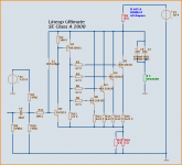
200 Watt idle
- 128 Watt across 8 Ohm Collector load
- 064 Watt 4 x MJL3281A
- 008 Watt 2 x 1 Ohm Emitter resistors
-----
sum 200 Watt
It is possible to squeeze out more than 10 Watt RMS
at >0.1% pure Class A type Distortion, ear friendly 2nd dominant
1 Watt RMS into 8 Ohm shows only 0.014% Dist,
mainly 2nd and some 3rd but hiigher are VERY very low
Enjoy")
Lineup
- 128 Watt across 8 Ohm Collector load
- 064 Watt 4 x MJL3281A
- 008 Watt 2 x 1 Ohm Emitter resistors
-----
sum 200 Watt
It is possible to squeeze out more than 10 Watt RMS
at >0.1% pure Class A type Distortion, ear friendly 2nd dominant
1 Watt RMS into 8 Ohm shows only 0.014% Dist,
mainly 2nd and some 3rd but hiigher are VERY very low
Enjoy
Lineup
Attachments
Hi Lineup,
Total system dissipation is 200 watt, but you will only get 50 watt rms from the load.
Each transistor dissipates only 30 watt. Problem with SE designs is that the sound falls apart totally when the four amps is exceeded.
I used a CCS instead of the 8 ohm source resistance. It is possible to wind a non-inductive resistor from wire but it may be quite large. I have in the past achieved this from using about 400 mm length of element wire from a broken toaster.
The THD figures looks good at around 0.2% at 100kHz. Harmonics increases evenly with frequency and the sound should be warm/friendly for lack of a better description.
Phase response is a 2 degrees over the audio band, but there is oscillation at about 7.5MHz. This can be overcome using a 220pF miller cap between collector/base of U1.
Otherwise, nice simple design. Build it and see what it sounds like.
In my opinion I would use a dual power supply, adjust the offset to close to zero and save on two caps, but this is not that important I guess.
Regards
Nico
PMA said:It is possible to get 2 x 30W / 8 ohm in pure class A from push-pull, at 200W input iddle power. Distortion much lower, than shown by lineup. Low order harmonics.
I would agree totally.
Hi,
you should be able to achieve +-22Vpk from a 50Vdc supply.
You can adjust the quiescent set point to achieve symmetric clipping.
This is about the 30W that the other respondents are predicting.
The 4Apk will allow the speaker impedance to fall to 5.5ohms.
This may suit a moderately reactive 8ohm speaker but probably not a severe reactance speaker.
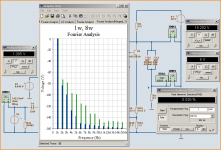
SE Class A 200W Fourier
.
I have trimmed the performance further.
Below is the FFT at 1 Watt and 8 Watt.
Especially 1 Watt looks just great. But also 8 Watt shows not much above -100 dB.
Even in reality, with real & good supply and real load, I think such an amplifier would sound very, very good
After all, we have no global negative feedback here and only one stage
using one Super Darlington Transistor.
Of course this amplifier need a very good, clean power supply.
Because PSU will effect the performance quite a bit.
I will try to make another 'light' version with 'only' 100 Watt idle.
As can be seen, besides the nice Harmonics,
the THD is 0.026% at 8 Watt RMS into 8 Ohm.
Lineup
Attachments
PMA said:I am not only predicting, it is my main amplifier and my design
Don't we all encounter this some time or other?
 - it is like who was first the chicken or the egg
My saying is, once you show anything to anyone, nothing remains sacred.
Anyway, whomever was the designer, the THD at 100kHz at 30 watt is only 0.2%, not too shabby at all and bandwidth extends past 1 MHz.
PMA said:Nico, frankly speaking, I did not get it now. I answered to AndrewT that my example of 2 x 30W/8 class A is a real amplifier, that I designed in 2002.
BTW, I think that you and me have many similar views of audio.
Hi Pavel,
yes I think we do share some common views. My comment is that there is no audio circuit that does not find its way into the public domain somehow.
Nico
PMA said:
BTW, I think that you and me have many similar views of audio.
Our age is starting to show

Nico Ras said:Our age is starting to show
yes, nicoHere are my first results from The 100 watt 'light' version.
Facts & Figures:
- 22k input Impedance
- 33 Volt supply
- 3 A idle current
- Single End (SE)
- 6 power bjt, MJL3281A
- Nominal load 8 Ohm
- Gain voltage ~6.8; +16.6dB
Comments:
How fast is ths amplifier?
Is no problem to get several MHz out.
As it works in open loop with very low gain; Gv ~6.8 (+16.6 dB).
But I have rolled it off at ~400 kHz.
The -45 degree phase response is at same frequency.
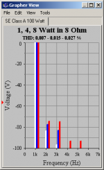
The THD figures (actually tells not much of expected sound quality).
1 watt: 0.007 %
4 watt: 0.015 %
8 watt: 0.027 %
----------------------------------------------------------------------------------
One General criteria for a good Class A amplifier is >=8-10 Watt output.
The fourier test below for 1, 4, 8 watt looks good to me.
Excellent 1 and 4 watt. Nothing above 100dB for higher harmonics than 2 and 3.
At 8 watt we are beginning to see some 4th and 5th. But no higher than those.
Enjoy
Lineup
Attachments
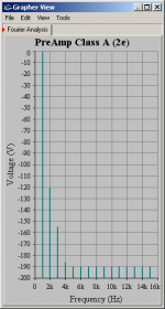
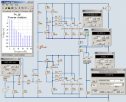
Class A Pre Amplifier part
.
The premplifier part work in Class A.
Only 2 stages.
PSU 1, +-25 Volt
PSU 2, +-30 Volt, output stage
Total Supply current 55 mA.
Gain x10, +20 dB
Power Bandwidth -3 dB at 10 MHz
Fourier Analys shows the perfect quality
Regards
.
The premplifier part work in Class A.
Only 2 stages.
PSU 1, +-25 Volt
PSU 2, +-30 Volt, output stage
Total Supply current 55 mA.
Gain x10, +20 dB
Power Bandwidth -3 dB at 10 MHz
Fourier Analys shows the
perfect quality Regards
Attachments
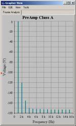
With a small change in my Class A super preamp
I managed to get the higher harmonics down further 20 dB !!!
The level of all above 4th is now -190 dB
And 3rd is at -155 and 4th is at -187 dB.
This amplifier uses only 12 Transistors in the 2 stages.
My circuit is unique and I have not seen the topology used before.
Only one time I saw some amplifier schematic that had a similar idea.
But it was not the way I do it.
Lineup
Attachments
MJL21193 said:Hi Lineup,
When I use Multisim analysis, having any other instruments connected to the circuit ruins the reading. I see a lot of stuff in yours above, but I'm not sure if these were there when you ran the Fourier.
You are looking for the "tube" sound maybe?
MJL21193
Yes, you are right. especially we should avoid to insert Current Measurements instruments. These are series elements.
Those can even cause instability in a MultiSim circuit.
In my circuit I have a couple of Volt meters in the output.
I do not think they effect anything. As they have very high impedance, in parallell.
And so takes only very tiny currents.
I could remove the voltage meter from the input, though.
Yes, tube sound.
My dream is to once build one nice Tube line preamp.
Maybe I will some time.
PMA said:I am not only predicting, it is my main amplifier and my design
PMA
I thought this was about my amplifier.
But maybe i am wrong
Lineup
Nico Ras said:
I used a CCS instead of the 8 ohm source resistance. It is possible to wind a non-inductive resistor from wire but it may be quite large. I have in the past achieved this from using about 400 mm length of element wire from a broken toaster.
--------
Regards
Nico
Nico.
My 100 Watt 'light' version (see test results above) uses one CCS of 3 x MJL3281A.
And the active part is another 3 x MJL3281A.
Still this version has only one supply (33V at 3 A) with 2 x 4700uF output.
I will have another look at your website http://www.digisec.co.za/ras/
I know you have done a lot of work with Class A.
Regards
Lineup
Push-Pull was suggested.
Above my light SE version (100watt running) shows 8 Watt 0.027% THD.
It uses one CCS for the output.
This below is one Push-Pull, running at 50 Watt.
Shows 8 Watt 0.228 % THD.
This is not even close !
What is wrong with the Push-Pull here?
What can I improve?
Because if Push-Pull is so great,
then I would be able to come close to those 0.027% THD.
At least !!!
Attachments
- Status
- This old topic is closed. If you want to reopen this topic, contact a moderator using the "Report Post" button.
- Home
- Amplifiers
- Solid State
- SE Class A 200W PURE Heat