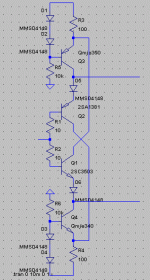
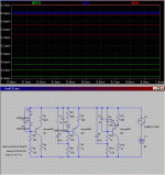
Dumb question, but what is Q20 doing ?
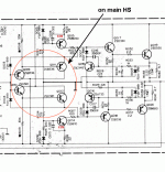
Q10/9 and the diodes give
you the 4 Vbe's (2.3-2.4v), which is too much(200ma bias per
device) ,Q20 shunts the extra .1 to.2v giving thermal compensation as well (it is mounted on one of the OP devices).
I might use the krill compensation but that would force
me to use 2 trannies and 3-4 diodes to achieve comparable
results.
Another good thing about this is if the Vbe fails, the worst
that can happen is overbiased outputs.
OS
Hi Peteostripper said:An externally hosted image should be here but it was not working when we last tested it.
This is looking good
")
Are you going to try TimS's diamond input stage?
I saw that you posted gleefully in that thread.
Q10/9 and the diodes give you the 4 Vbe's (2.3-2.4v), which is too much(200ma bias per device) ,Q20 shunts the extra .1 to.2v giving thermal compensation as well (it is mounted on one of the OP devices).
That's what I suspected, but as it shunts the current through Q9 and Q10 won't that tend to turn one of them off?
Wouldn't reducing the value of R15 an R24 have the effect of reducing the bias voltage but keep Q9 and Q10 biased on.
Hi all.
I wish it was possible for me to follow this thread, as a man can only get so much reading done in a day.
However, I looked at one of the attachments and saw this possibility. It looks like discussion has moved forward a bit since then, but I thought I'd post anyways.
Doing this will pretty much double the gain of Q10 and Q9. Connecting the collector directly to mains is safer stability-wise, I think, but maybe we can see what this comes up with.
- keantoken
Attachments
I wish it was possible for me to follow this thread, as a man can only get so much reading done in a day.
I have not even been following this thread, too busy hunting down info on diamonds
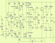
ground referencing the current sources has it's good and bad points. The plus is better regulation, while the downside is
a degradation of PSRR. In the attachment decoupling caps
are used. I still have to simulate all the mods to this basic
topology and see how they affect OP biasing,PSRR, and
loop gain.
By asking a lot of questions on the other 3 diamond buffer threads (Krill , DC300, and diamond amp) as well as
having the schema's for the dc300 and nakamichi 620
(both diamond based) I have enough to go on now.
I have the basic buffer built and running and it is very stable
so FA4 is on it's way
.OS
Attachments
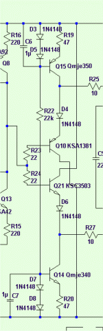
Not what I meant, actually... Look at the emitters of the MJE340/350's. Although I'm not sure how well this works since I couldn't get the whole Q10/Q21 thing to work anyways.
If you are worried about PSRR, you can improve that by doing this... schematic attached.
I'm not sure what you mean by regulation, as I've only heard that in reference to regulators. I still have yet to learn some of my terms.
- keantoken
If you are worried about PSRR, you can improve that by doing this... schematic attached.
I'm not sure what you mean by regulation, as I've only heard that in reference to regulators. I still have yet to learn some of my terms.
- keantoken
Attachments
I will double post, so I can add another attachment... Sorry.
Your two-diode CCS will lose output current as it gets hot. I don't know if this will be a problem even in a closed box, but I will say this anyways.
This is pretty much the current mirror we discussed in Dan's thread. This will have much smaller temperature drift. Don't be fooled. Even though we substituted one diode for a resistor it still has better PSRR than your original two-diode CCS without the bootstrap cap.
- keantoken
Attachments
by beantoken - Your two-diode CCS will lose output current as it gets hot
That is why some opt for LED's,... better thermal characteristics.
one could also use a precision IC current source
http://www.national.com/mpf/LM/LM334.html
or zener while weighing complexity and part count against
performance..
The decoupled 2 resistor approach is standard in the blameless
design and works good. Another point, since I am wrapping
the feedback loop around the WHOLE amp, PSRR in the current stage is not going to be as big an issue as it would be for the Krill.
Go to my WWW and click frugalamp link below "cheetah" and time, open FA3 folder, download [ FA3K.asc ] .. it sims purrfectlyNot what I meant, actually... Look at the emitters of the MJE340/350's. Although I'm not sure how well this works since I couldn't get the whole Q10/Q21 thing to work anyways.
OS
AndrewT said:Hi Kean,
could you substitute a red LED for the twin diodes?
I hear that a red LED has a similar temp co to a BJT.
I would like to see both the ripple and the temp variations.
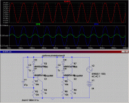
The ripple is indeed less.
This is the tempco simulation. This doesn't show in the graph, but the current through the LED CCS actually rises as it gets warmer, while the others get lower. I hope I did this right. The LED is biased at around 10mA.
I used a red LED model I found via Google, not sure how accurate it is.
- keantoken
Attachments
I'll assume I've got the right to double post now since I'm the man with the sim.
I was googling and found this:
Has anyone tried this? I don't think a simulator will do this right. I think I've read this in an application note or something also.
Perhaps mr. Christer or someone can set us up some good measurements.
- keantoken
I was googling and found this:
For protecting mosfets (zener as a shunt across gate and source) I have used with good success a reverse biased base-emitter junction of generic BC550 or BC560. Capacitance is low and the zener voltage is quite the same across different devices.
Cheers,
Gerhard
Has anyone tried this? I don't think a simulator will do this right. I think I've read this in an application note or something also.
Perhaps mr. Christer or someone can set us up some good measurements.
- keantoken
I did the diode vs. LED test and the LED wins..
(see attachment)
PSRR wise
In an actual circuit with the cap (like the FA2 I'm listening to)
the LED beats the diodes by 10 more db(most likely the cap)
and has almost no thermal drift. BUT "strait up' with no
decoupling, the led beats the diodes by just 1 DB.
Next post I will use the decoupling techniques from the nakamichi
620 which compensates the current source differently.
OS
Attachments
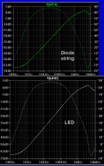
Which LED model are you using?
The QTLP690 fairchild 1.8V red led.
In the whole scheme of things
the PSRR/ripple factor of the diamond CCS's really only
help to stabilize the
biasing of the OP stage (vbias). The whole diamond buffer
is corrected by NFB so the current sources are just overkill.
In the Krill, they are using a dual voltage supply even with
current sources ,but the Krill does not wrap the current stage
with the NFB loop.
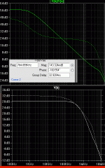
Attached below is the (I think) close to final plots that I
really like. (perfect gain to 100k and 100db phase margin).
The diamond seems to extend the bandwidth of any
standard amp by some degree and allows for a unloaded, low
current VAS as a bonus..

OS
Attachments
DB's do sound good. I find them better than simple EF's. If you listen to an open loop DB you'll find they sound very transparent.ostripper said:
Attached below is the (I think) close to final plots that I
really like. (perfect gain to 100k and 100db phase margin).
The diamond seems to extend the bandwidth of any
standard amp by some degree and allows for a unloaded, low
current VAS as a bonus..
OS
Hi ostripper. I'm trying to catch up here after a couple of days without Internet service.
Run open loop, as I do, my amps have a very low output impedance and excellent speaker control. I prefer the sound without feedback so that is how I build. Distortion specs are also very good run open loop and there is no chance for the stage to become unstable or oscillate. As an added bonus, if the output to the speaker gets shorted you don't loose the feedback and go OLG.
I never really worried about what would happen if the compensation (diode string in my case) failed. If it shorted it would simply reduce bias. This would affect the sound some, but do no real damage. If it opened it will blow the line fuse. With less than 0.1mA of current the diodes should never fail. It is always possible for a connection to break however, so I will add a resistor in parallel with the whole string to set a maximum bias in this event.
Thanks for pointing out this potential problem.
I am attaching a simulation result showing the output stage only, run open loop with a 20V input. As you can see it shows a 3dB down point at only 3 MegHz. A test on a real unit only gave about 1.5 MegHz. Still, I think that is good enough for audio.
Attachments
Thanks for pointing out this potential problem
I didn't mean to point out a problem , but I don't want to be
a contributer to burning amps .

I've tried both including or omitting the diamond current
stage in the NFB loop with little effect other than ,with the
isolated current stage, no change with load. (As you pointed out.)
Another interesting note is that by degenerating the darlington
(470r - 2.2k) like a standard EF type 2, "tames" a little
bump at 5MHz (I think that is where this thing "likes" to oscillate)
and sets the phase margin.
I already did the carlos thing and no
fire , so I know it works. I tested what would happen if my vbias died and itis the safest I could imagine.. just 300ma (severely overbiased).
Idiot proof, much better than a typical amp. A total short at
the output would just burn the basestopper resistors.
It seems DIYaudio has gone "krill crazy" these days, even
carlos (no trashbin or buckshot) likes it, 3 seperate diamond
topology threads... you started it all ,steve, thanks!
BTW..., yours(krill) is most like the Nakamitchi 620, except they use an EF'ed diamond which is the thermal compensation .
(attached)
OS
Attachments
- Status
- This old topic is closed. If you want to reopen this topic, contact a moderator using the "Report Post" button.
- Home
- Amplifiers
- Solid State
- The Frugalamp by OS