Looking much more like a single pole response now. Good stuff. Try right-clicking on the V(b)/V(a) expression at the top of the graph, and putting a minus sign in front of it in the expression editor dialog. Then click OK. Left-click on the -V(b)/V(a) expression. That will activate the measurement cursor. Move it until you find the frequency at which the magnitude is as close to 0 dB as possible. What is this frequency? And what is the phase shift at that frequency?
ostripper
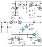
just one little detail: R3 10k in long tail pair
BC546 can take 60 Volt, so you need no such resistor.
It does not do any good.
Probably does things a bit worse")
As Douglas Self tells us:
just one little detail: R3 10k in long tail pair
BC546 can take 60 Volt, so you need no such resistor.
It does not do any good.
Probably does things a bit worse
As Douglas Self tells us:
DouglasSelf said:http://www.siliconchip.com.au/cms/A_110797/article.html
is a copy of the Blameless design,
carefully including a mistake I made.
(putting a resistor in the input tail - bad move)
Attachments

ostripper said:Andy, freq. is 344khz , and phase is -96dB.
Looks like the amp is a bit overcompensated.
Try finding the frequency at which the phase shift of the loop gain is -100 deg. This will be a frequency larger than 344 kHz. That's what you want to be your new unity loop gain frequency. To increase the unity loop gain frequency, you can decrease the input stage emitter degeneration. Try decreasing it in the same ratio that you're increasing the unity loop gain frequency. That is, if the new unity loop gain frequency is e.g. 500 kHz, the new input stage emitter degeneration resistor should be 344/500 times the old one. Replace 500 by the actual frequency in kHz at which the phase of the loop gain is -100 deg.
By lineup - To change CCS current in input you use R8, 220 Ohm
Mr. self has said other things ,too but do we always listen to him?? he said a balanced VAS was too much trouble, but I'm
not listening.
One thing at a time. your idea is good but the load on my LPT
is in the uA's (EF'ed VAS's)balanced as well. With a different amp, like frugal 1, I will try this.
BTW , I figured out how to import .models and made my own
LTspice libraries (custom)..thanks
OS
Sorry for confusion , those figures are with the updated 68R,s.I'm confused. At 536 kHz, the gain should be less than 0 dB right? Which means you'd like to decrease the emitter resistors in the input stage to get it back to 0 dB there. Or did you already tweak the input stage emitter degeneration?
Great! Looks like you've really made some great progress here. I'm signing off for tonight, but if you're around tomorrow, maybe you'd be interested in playing with transient response in SPICE. With that tool, you can look at square waves and such, and verify that you have no overshoot or other problems which sometimes only show up in transient.
ostripper said:Thank you andy, for patience. Are you a teacher.? You have a
very professional and concise way of getting your point
across.
OS
I have to agree, the info generated in this thread is thoroughly interesting, especially Andy's input
Great thread
Soon I will build this (next week). Gives a real sense of satisfaction to start at conception and go to listening
in just a week.
Stay tuned, because I will go all out to show how to make a
near toner tranfer quality board with good layout the "frugal way"
(no computer involved).
in just a week.
Stay tuned, because I will go all out to show how to make a
near toner tranfer quality board with good layout the "frugal way"
(no computer involved).
Your not the only one ,Hugh. This amp is tricky...
First I wanted to keep the LTP very balanced..got that..
R17/13 do that.
(blue and green lines)
1/1000th of a MA... but that threw the unity gain point UP(1mhz)
R17 also changes OLG. yikes!!
but with andy's pointers, changing Cdom and LPT degen. Resistors brought it back in line.
All this tinkering really smoothed out the slope as well as
creating real balance on both the LTP and VAS.
First I wanted to keep the LTP very balanced..got that..
R17/13 do that.
An externally hosted image should be here but it was not working when we last tested it.
(blue and green lines)
1/1000th of a MA... but that threw the unity gain point UP(1mhz)
R17 also changes OLG. yikes!!
but with andy's pointers, changing Cdom and LPT degen. Resistors brought it back in line.
An externally hosted image should be here but it was not working when we last tested it.
All this tinkering really smoothed out the slope as well as
creating real balance on both the LTP and VAS.
lineup said:ostripper
just one little detail: R3 10k in long tail pair
BC546 can take 60 Volt, so you need no such resistor.
It does not do any good.
Probably does things a bit worse
As Douglas Self tells us:
Lineup
In the SCULD2 schematic that you posted, you will see that >270mW would be dissipated in the BC556 without that resistor. The BC556 is rated for 500mW maximum dissipation.
I believe that this would detract from the CS stability,unless at the very least it was fitted with a heatsink clip.
SandyK
Sandy, I see what you mean.
But in my book, 270 mW is not too much for 500 mW rated TO-92
it is a high level, but in no way critical
50-60% of max is msot times alright.
I personaly can think of running at 350 mW .. but preferably not more.
Why I posted that schematic, is because Douglas Self refered to it,
as to show, that copycats of his schematics, whithout their own knowledge,
will copy even when the original designer made a mistake.
And in this case D. Self called his including of that resistor:
a mistake (bad move).
And I also never have used such resistors from the LTP CCS.
Instead, if we need, we will use one transistor,
that suits our amplifier requirements.
Regards
Lineup
- Status
- This old topic is closed. If you want to reopen this topic, contact a moderator using the "Report Post" button.
- Home
- Amplifiers
- Solid State
- The Frugalamp by OS