Here is one MODEL for 2SC1845, from PSpice.
I will add this transistor to my MultiSim library
I will add this transistor to my MultiSim library
filename: jbipolar.lib
* Library of Japanese Bipolar Transistor Models
* Copyright OrCAD, Inc. 1998 All Rights Reserved.
* $Revision: 1.8 $
* $Author: rperez $
* $Date: 17 Nov 1998 10:47:02 $
=====================================
.MODEL Q2SC1845 NPN IS=1.485E-12 BF=674.1 VAF=100 IKF=10.01E-3 ISE=1.485E-12
+ NE=1.883 BR=2.734 VAR=100 IKR=10.01E-3 ISC=1.485E-12 NC=3 NK=.3535 RC=1.704
+ CJC=5.210E-12 VJC=.35 MJC=.2694 TF=909.9E-12 VTF=5.724 ITF=134 TR=10.00E-9
*$
MJL21193 said:
Now, don't get your panties in a bunch Rachel.
I know your opinion, I'm just trying to do a little myth-busting. My point: how can it sound better?
The increase in distortion was not a slight on my part (it's only a difference of .001%). I'm sure it could probably be implemented to lower THD.
Yor sim results are misleading and pointless because they do not have the sub ppm resolution to show the true effect of the improved current mirror (swamped by much more dominant sources of nonlinearity).
Also, that's Elaine in the avatar now.
Cheers,
Glen
G.Kleinschmidt said:I offered the 3-T current mirror as an alternative to that diode thing in another thread and further on made clear my opinion on the general worth of implementing it.
Cheers, Glen
Glen
")
You make it sound as you invented that Mirror and Owns the Patent.
Perhaps you were around to tell those designed NE5534 to put it in
I would guess not. That mirror can be seen all over.
And for very good reasons!
Because yes, for AC applications (audio amplifiers) it is one of the best.
My simulation comparing tests, yesterday and today confirms the merits.
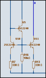
The actually optimal operation can be sharpened, by selecting and trimming the values of those 3 resistors.
To fit the circuit in question
I show one example with resistor values used for my 100kHz testing today.
At 1 mA current.
Attachments
G.Kleinschmidt said:
Yor sim results are misleading and pointless because they do not have the sub ppm resolution to show the true effect of the improved current mirror (swamped by much more dominant sources of nonlinearity).
How much precision do you need? The resolution of the simulator is high enough to see a difference that would be audible.
I'm sorry, I'm not seeing any improvement at all. Not in the THD figure or the current through the LTP.
Lineup said it - you act as if this is your girlfriend I am dissing. Take a break.
This should be over in the CM thread maybe. We are cluttering up OS's thread.
I guess I have comments...
the collectors to see the difference in voltage..
LTP voltages
1. standard CM - .11v (very loose matching in the lot I
have.. plus I was lazy and just wanted to hear it.)
2. "frugalamp mod" (second schema)- .003v
3. as above , but with diode /trimmer on NFB side of LTP
<.1 uA (that's microamp)
What I really used is a KSC 1845, as this is all mouser had,
<1pf Cob ,high Vceo, only problem its pinout was ECB, which
screwed up my placement. (which I could solve with thermal
epoxy for thermal EQ.)
CCS does not need to be high gain, is very important to
amp,BD is cheap, and I might want to jack up the current
to the Diff. (2.0v green led=3ma LPT/17ma VAS ..so let it run cold....
What is strange , your mention of this on the thread happened
right at the time I was testing it. And it is the mod, when applied,
that you can really HEAR.
them up and email them to me.. I actually had to use MJ15003/4
models for this amps output. With these ancient but good OP's
It modeled out at .01/1KHZ and .03/10KHZ
By the way , N. pass mentioned the "woody" amp in the CM
thread......
.. here it is..

Thanks, OS
When I explored this variable I placed the meter acrossBy Sandy K - Are you able to post the LTP collector voltage readings, before and after the 3 transistor CM ? THis would give a very good idea of the differences between the 2 types, and the degree of balance achieved.
the collectors to see the difference in voltage..
LTP voltages
1. standard CM - .11v (very loose matching in the lot I
have.. plus I was lazy and just wanted to hear it.)
2. "frugalamp mod" (second schema)- .003v
3. as above , but with diode /trimmer on NFB side of LTP
<.1 uA (that's microamp)
By MJL - I like the choice for differential pair - I have a multitude of these salvaged from old Kenwoods myself.
What I really used is a KSC 1845, as this is all mouser had,
<1pf Cob ,high Vceo, only problem its pinout was ECB, which
screwed up my placement. (which I could solve with thermal
epoxy for thermal EQ.)
by jaycee - I'd stick with the regular current mirror in the LTP. Also the current sink for the LTP doesn't need to be a BD139, you can use a BC546 just fine.
CCS does not need to be high gain, is very important to
amp,BD is cheap, and I might want to jack up the current
to the Diff. (2.0v green led=3ma LPT/17ma VAS ..so let it run cold....
By G.Kleinschmidt - Just for fun, I'll note that the current mirror currently celebrated as the most sonically satisfying by more than one member is the 3-T version suggested by yours truly.
What is strange , your mention of this on the thread happened
right at the time I was testing it. And it is the mod, when applied,
that you can really HEAR.
Since you have all these spice .LIB files could you just winrarBy lineup - Here is one MODEL for 2SC1845, from PSpice.
them up and email them to me.. I actually had to use MJ15003/4
models for this amps output. With these ancient but good OP's
It modeled out at .01/1KHZ and .03/10KHZ
By the way , N. pass mentioned the "woody" amp in the CM
thread......
.. here it is..
Thanks, OS
By MJL - I know your opinion, I'm just trying to do a little myth-busting. My point: how can it sound better?
It just does. Perhaps it has something to do with slewing
positive vs. negetive(AKSA first mentioned it gives better decay
at HF).
OS
By steve Dunlap - Where in TN are you located (if you don't mind saying)?
I,m not that far away.. Knoxville , on the Oak ridge
(I'm glowin') side of town
(I-40)...
OS
Congratulations, Pete,
You've done good - that's a nice amp, even if the name is a shade tumescent.....
The superior decay at HF also translates to better resolution. Many of these subtle changes you CAN hear, and you can really hear caps.
It's wonderful to see people building stuff.
Glen, you really will make a spectacular old man. What are you now, 35?
Hugh
OS,
The third transistor might reduce peaking in the ac frequency response. This is speculation on my part but is a phenomen that occurs with the standard Widlar that the patent circuit (Nakamura) corrects.
I have to agree with Hugh, you have done some fine work here probably to the annoyance of some members but what the heck....It's how it sounds thats important......keep up the good work.
I have attached a logo which you might want to consider to use on your amp least someone gets the wrong idea about the name.
Best regards,
Jam
Attachments

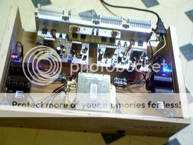
Hey . what's up, Hugh. This amp really sounded good , but
the wifey didn't want me to burn up the babies ,so I have to
put it in a case which means I can not listen to it for a day..

I,ll have it together again (tommorrow)
It looks a little "lifeforceish", aye. I must ask you a thermal
comp. question. I have heard that as well as electrically, one can
use physical isolation to "trim" the Vbias (BD139 on OP tranny)
using ungreased mice or other semi- insulating material.
Have you had any experience with this..please comment.
Thanks again , Hugh.
OS
the wifey didn't want me to burn up the babies
,so I have toput it in a case which means I can not listen to it for a day..
I,ll have it together again (tommorrow)
It looks a little "lifeforceish", aye. I must ask you a thermal
comp. question. I have heard that as well as electrically, one can
use physical isolation to "trim" the Vbias (BD139 on OP tranny)
using ungreased mice or other semi- insulating material.
Have you had any experience with this..please comment.
Thanks again , Hugh.
OS
OS,
And they say burning babies only happened in the Dark Ages!!
Yes, on all my amps I use a BD139 Vbe multiplier simply clamped down on top of one of the outputs. The drivers have their own heatsinks, separate from the mains, which get slightly warmer. I use 1K5 on the C/B leg, and with a DEF II I find that when it gets hot, it very slightly overcompensates, pulling down the quiescent from 60mA to around 52mA. This lasts until the heat dissipates when it returns to 60mA. At first switch on quiescent is first 55mA, rising within about ten minutes to 60mA. This all depends to a minor degree on ambient temperature, but it's very reliable, and utterly repeatable.
I can vouch for clamping it direct to the output device. No grease is required or used.
Cheers,
Hugh
Re: I guess I have comments...
Since you have all these spice .LIB files could you just winrar
them up and email them to me.. I actually had to use MJ15003/4
models for this amps output. With these ancient but good OP's
It modeled out at .01/1KHZ and .03/10KHZ
------------------------------------------------------------------
for 1302/3281 we should use andy_cmodels
I have done some tests on those models. They are excellent!
Read andy_c article and download Spice MJL1302A/MJL3281A:
http://andycpublic.50webs.com/spice_models_1.htm
PS. these Models should be possible to use for
MJL3281, MJL3281A, MJL4281A, 2SC3281, 2SC5200, FJL4215
MJL1302, MJL1302A, MJL4302A, 2SA1302, 2SA1943, FJL4315
.. because they are all very similar or even same devices with different names
have to agree with Hugh, you have done some fine work here probably to the annoyance of some members but what the heck
Now why would good work offend anyone ?? It is just more
to absorb. After reading
D. Self's amp handbook I was shocked to learn he was a member here, so I got in on one of his threads and commented on
his fine work.
I give carlos (DX) the "doer", Quasi (who, by the way does not
make firehazard amps), and AKSA (for the tips and pictures
on his site) for the inspiration on "how to do it"
Enough "strokes" What needs to be done is make a killer
all in one protection circuit (opto isolator based) and
document the layout so I can contribute.
Any help with Eagle and P/LT spice would be welcome.
OS
Thank you lineup.. A question ,the model, just save it as a .LIBBy lineup - for 1302/3281 we should use andy_cmodels
file ,because it is just a txt file on andy C's site..??
or can you import a txt directly into your model library??
By lineup - Here is one MODEL for 2SC1845, from PSpice.
-------
Since you have all these spice .LIB files could you just winrar
them up and email them to me..
Ostripper.
These models I have downloaded file by file !!!! from this nice greek guy.
You can browse Parent directory, too and more files,
but go for xxxxxxx.lib = PSPICE format in here:
http://power.teipat.gr/download/OrCad/OrCad Libraries/Library for Capture/PSPICE/
Lineup
I have attached a logo which you might want to consider to use on your amp least someone gets the wrong idea about the name
Its "woody", it's made of wood.. Blame Nelson Pass, he came
up with the name.. (current mirror discussion - post 151)
OS
ostripper said:
Thank you lineup.. A question ,the model, just save it as a .LIB
file ,because it is just a txt file on andy C's site..??
or can you import a txt directly into your model library??
You can try import first, depends on your sim, what functions have
In MultiSim, I use the component wizard.
Then for the models, I can import one file, with whatever extension.
But only one transistor in each file.
Most often I add one transistor at the time
by Copy and Paste from my textfiles, into MultiSim Component Wizard
Because I haven't found my MultiSim can import many transistors from one file.
Some spice softwares can import filename.lib
lineup said:Glen
You make it sound as you invented that Mirror and Owns the Patent.
Oh, obviously
MJL21193 said:How much precision do you need?
I told you.
MJL21193 said:Lineup said it - you act as if this is your girlfriend I am dissing. [/B]
Are you kidding?
- Status
- This old topic is closed. If you want to reopen this topic, contact a moderator using the "Report Post" button.
- Home
- Amplifiers
- Solid State
- The Frugalamp by OS