Hello
These was my first DIY amplifier , I built about 20 years a go .
Now I think to rebuild it . From beter quality parts .
Any comment welcome .
When firs I built it I used one pair power transistors but after I added one more pair which brought a lot of improvement in the sound .
More dynamic , more bass , I used +/-56V power supply with two pair 50 000uF Mepco capacitors .
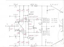
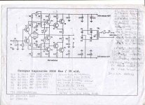
I post the schematic you can take a look . No need for preamplifier , just a 10K pot. . On the input is better to use a bit higher value capacitor .
One more time any comment ,advise welcome
Greetings
These was my first DIY amplifier , I built about 20 years a go .
Now I think to rebuild it . From beter quality parts .
Any comment welcome .
When firs I built it I used one pair power transistors but after I added one more pair which brought a lot of improvement in the sound .
More dynamic , more bass , I used +/-56V power supply with two pair 50 000uF Mepco capacitors .
I post the schematic you can take a look . No need for preamplifier , just a 10K pot. . On the input is better to use a bit higher value capacitor .
One more time any comment ,advise welcome
Greetings
Attachments
looks like what I call emitter feedback (curr-fb )
but I have never seen this very type before
something new to me = more interesting
practically all transistors can be upgraded, improved
personally I should start with +-30 Volt
and try to make it work/sound perfectly with one output pair
another thing
these type often benefit much with separate power supply for output stage
and the input/driver part a well regulated own supply
Hello lineup
Thanks for your advise , the separate power supply I think probably is a great idea .
We did tried with lower power supply voltage and after adjust the bias but the amp lost a lot from the dynamic from the bass and from the control over the speakers .In a simple sentence the sound get somehow thin and weak .
We even tried to adjust the resistors, using lower value, calculated after the lower voltage but it didn't help at all.
So that was the reason we doubled the power transistors .
Another reason at +-56V those Darlingtons produced a lot of heat , to solve the problem we decided the best would be 2 pair output transistor . To spread the heat better .
Clearly I remember that gave to the amp more dynamic and better bass more authority ower the speakers.
By the way it sounded really sweet and nice , a bit warm like (I could com pair the sound of the amp to the Hiraga Class A , or like Naim like , somehow a bit warm sound ) so that is the reason I think after 20 years I would give another try again .
But now I try to improve the passive components , better quality resistors , and capacitors . like Dale resistors and Cerafine or BG capacitors at least to the low voltage type . Some silver mica capacitors instead the cheap ceramic caps .
For power transistors we have not to many option here .
We tried Motorola MJ11015/16 Darlington but get worst . There is not to many Darlington on the market . Very few amp was built from Darlington transistors .I know Hiraga Class A etc used the Darlington circuit but not the transistor it self . And we tried to use TIP142 /147 but BDW83C under the name of Morocco , or Texas Ins. was the best .
Philips had some good Darlingtons but today discontinued parts very hard to find and even they ask $30 for a piece .
We built the Darlington schematic out of Toshiba transistors but somehow it get the amp much slower .
BF transistors are high voltage type so for the 56V power supp we needed that . But today we can find from ON Semi maybe better driver transistors with high voltage .
One of my friend after 20 years still use these amp and very happy with .
I gave him a Symasym kit with good parts but after he built it He told me "thanks but I stick with my old amp."
Thanks one more time for your advise .
Greetings
Hi gaborbela,
Nice amp. Interesting.
It looks almost like a unity diamond buffer, but you are modulating a "current sources" for gain. Interesting.
From my work with similar circuits, the doubled outputs will give better damping and life to the music. It probably sounds slightly compressed at higher levels, but with good detail. Can you stabilize the bias with lower value emitter resistors? Say 0.22 R? Even 0.33R would be an improvement. Adding more outputs will improve the sound also, not for heat spreading but to lower the range of current each output gets.
Coupling the bias transistor thermally to the drivers should help to control the bias current a little better than if they were on the heat sink. All you can do is try this. You will want to keep the input pair as cool as you can. Getting the bias to stay right is a balancing act sometimes.
Running the voltage amp stages (from the fuses back) off regulated supplies might help with any interference from the outputs, but your diodes will at least decouple from sudden drops in the unregulated voltages. You were thinking of this I bet.
Do you have a picture of the completed amplifier? An inside shot might be nice.
-Chris
gaborbela said:One of my friend after 20 years still use these amp and very happy with.
I gave him a Symasym kit with good parts but after he built it He told me "thanks but I stick with my old amp."
") would tell us something about the potential of this amp
would tell us something about the potential of this ampbecause not many dare to call SymaSym is a bad amplifier - because it is not
If you want to stay Darlington in one package,
Sanken has got some really Fast!!! MONSTER 200 Watt darlingtons
npn, 2SD2561 ... fT typ 70 MHz, Cob 120 pF
pnp, 2SB1648 ... fT typ 45 MHz, Cob 320 pF
Sanken Datasheets
http://www.allegromicro.com/en/Products/Categories/Sanken/Transistors/
from
www.AllegroMicro.com with many resellers
Sanken has got some really Fast!!! MONSTER 200 Watt darlingtons
npn, 2SD2561 ... fT typ 70 MHz, Cob 120 pF
pnp, 2SB1648 ... fT typ 45 MHz, Cob 320 pF
Sanken Datasheets
http://www.allegromicro.com/en/Products/Categories/Sanken/Transistors/
from
www.AllegroMicro.com with many resellers
HI
First I want to say all my respect to Mike B and his Symasym amplifier ,is really nice amp !!!
My friend told that thanks but he does not want from sound of the Symasym .
When I ordered from China the Symasym PC boards the min. order was 5pc. So I ordered 6PC and I sent a full kit to my friend to Budapest .
Yes the amplifier is very stable firs we used .33R emitter resistors but after we doubled the output the amplifier designer advised to us to increase a bit those resistors .
Of course the BD136 must be on the main heat sink .
It need a bit larger heat sink than the usual classic Class A/B amplifier , somehow the Darlington tend to run hot .
Right now I don't have the amp , only my fried still has it after 20 years .
When I built first these amp I had a pair Revox vintage tube mono block amplifier upgraded by a tube amp designer but after I start listening to these amp I sold those .
I like power amplifiers with big VU meters so from the ad I look up a Sansui power amp about 45lb but when the owner brought to my home to test it we com pared with these amp and He didn't believe to his ear . He started to look to the speaker cables if these amp runing or something else.
Of course it sounded much better than his Sansui power amp .So he took his amp home .
Another guy try to sell me a Tehcnics power amp (the old type) but with the same result. (Today I have a large Akai PS-200M power amp with big blue VU meters but need to be rebuild both side are dead about 70lb . )
The amplifier was design by a Hungarian electrician engineer .
20 year before I was totally a greenhorn in DIY . I did try to improve the sound buy testing all kind of transistors , capacitors until I destroyed the PC board . Of course with out any success only improved from the double power transistors and higher voltage . The designer advise was that to.
One day I played with the amp and I burnt one of my woofer so I took the amp into parts and I trow the PC board to the garbage .
Now I did share the schematic with another(DIY-er) fried Tymo and he wrote he will design me a new PC board when he will has time for .
So I hope soon can rebuild it again .
Thanks for your advise .
Greetings
Hello
Here is the data of the BDW83C Darlington transistor .
http://www.st.com/stonline/products/literature/ds/4265.pdf
I'm still learning about the semiconductors so I'm not sure I can replace these with those Sanken type .
Greetings
Here is the data of the BDW83C Darlington transistor .
http://www.st.com/stonline/products/literature/ds/4265.pdf
I'm still learning about the semiconductors so I'm not sure I can replace these with those Sanken type .
Greetings
Hello Anatech
I just reread your post and now I understood your advise about the bias transistor .
I think is a good idea because how I wrote the power transistors tend to run a bit hot .
Before the bias transistor was on the main heat sink .
I will ask my friend when he design the PC board to design that way so we can use a small heat sink for the drivers and the bias transistors together .
Before it was on the main heat sink .
One more time the circuit not my design , I wish I could do that !
Thanks
Greetings
Hello
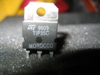
If someone interested on these amp only high power transistor which worked the best in these amplifier is from the next company .
Or the badge ST or the writing MOROCCO have to be on the case of the transistor .
I did try to use BDW83D made by another company but just a waste of money .
I purchase 10pairs and all gone to the garbage .
You can argue about these statement but please take a look at the transistor circuit . Two transistor in one case 2 resistors and a diode .
I post a picture from one transistor made by the same company .
TIP142/147 is similar but most be from these company .
I did purchase those transistors to from different company but bad result .
I do not advertise these company these only the result of our tests .
The transistor package can be TO218 or TO247 .That is not important .
Like on the picture
Attachments
Attachments
Those transistors (MOROCCO) are having
STMicroelectronics logo
http://www.st.com/
Here we have a page with most all LOGOS for semiconductors
Bookmark:
http://www.dibsplace.com/design/ICLogos.htm
STMicroelectronics logo
http://www.st.com/
An externally hosted image should be here but it was not working when we last tested it.
Here we have a page with most all LOGOS for semiconductors
Bookmark:
http://www.dibsplace.com/design/ICLogos.htm
gaborbela said:Hello
Here is the data of the BDW83C Darlington transistor .
http://www.st.com/stonline/products/literature/ds/4265.pdf
I'm still learning about the semiconductors so I'm not sure I can replace these with those Sanken type .
Greetings
No, they are probably way too fast
Better you try to use some that you or somebody else know is working.
Hello
The first schematic the original with the Darlington transistors !
I had the same schematic with the fuses but I took those stupid fuses out with the 1uF capacitors .
I'm still mad about those fuses .
It degrade the sound badly and in case for some reason one side would blow up your speaker go with .
I know it happened with me .All the 56VDC ended up on my speaker coil . Is a very bad idea . To protect a max $3 value transistor which can take 10A with a 2A fuse and let your speaker blow up instead!!!! That is very stupid. So I took out both fuse after I payed the heavy learning price for .In another way more safe with out those fuse . 10A give you more protection than 2A.
And if we double the output transistors ....we just need the right size heat sink .My friend has the amp from that time ..
I meet with the designer about 20 years a go when he gave me these schematic . He just took a piece of paper and scratched on these schematic at the front of me from his head .I still have it but now hard to read . After almost 20 years ..
After he gave me the second schematic to , after I told him the amp took my speaker out (which you say orig) but he warn me the first one much better amp .So that was the reason double the power transistors .
I did tried the second version which you posted as original but to com pare with the Darlington heaven and earth .
And I used high quality Toshiba power and Motorola driver transistor .
Slow like a 80 years old design. No sharpness , no punch , no control over the speaker etc .
Very slow with those transistors . I would not build that if I do not listen music anymore .
Thanks you for posting that Hungarian tread I will go on and study it .
lineup thanks for your help but I already did look up the transistor data and not the same and the circuit either different.
There are many different type of Darlington circuit .
I have a Philips ECG catalog and I have there at least 11 type.
Different resistors , diodes etc .
Greetings
Hello
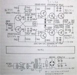
I should correct myself .I built the firs schematic posted by Ferencz and the second amp it was the third schematic .
For me that amplifier Canopus sounded horrible .So after a few tests and modification I decided that is not even a HI-FI amplifier category .
To be clear I didn't tried the Japanese version .
Out of my experience I'm only interested the Darlington version amplifier !!
That is more than a great amp to me .I have some feeling in my heart to it like one of my best friend ,I would like to meet him after those years ...
Greeting
- Home
- Amplifiers
- Solid State
- My first DIY amplifier 20 years a go