My tests will take time. I've been hijacked to another city by relatives !") So I will have to first attend to 'family related' matters and that will last another 2 weeks !
So I will have to first attend to 'family related' matters and that will last another 2 weeks !
I really like the Latfet sound though it would mean using a separate bipolar amp for LF duty. The bipolar power devices appeared to have 'meatier bass' ! But to be sure a very careful controlled test is required. I can't do that at the moment as I don't have enough boards.
Maybe Latfet for mids and HF and bipolar for the LF in a bi-amped system ! I could implement this easily as I have a few speakers wired for biamp use.
Wonder if anyone else has tried that already ?
So I will have to first attend to 'family related' matters and that will last another 2 weeks !I really like the Latfet sound though it would mean using a separate bipolar amp for LF duty. The bipolar power devices appeared to have 'meatier bass' ! But to be sure a very careful controlled test is required. I can't do that at the moment as I don't have enough boards.
Maybe Latfet for mids and HF and bipolar for the LF in a bi-amped system ! I could implement this easily as I have a few speakers wired for biamp use.
Wonder if anyone else has tried that already ?
Just remembered about this thread !
I didn't get round to doing anything about this amp. Been too busy with several things. Maybe I should do something now. Just rigged up my new computer and want to use ARTA on it and see what measurements I can take.
I have a couple of other completed amp boards to compare it with. Mono for the moment.
Wonder if anyone else got time to complete their boards and compare the amp with something else. By itself it did sound quite good. But now I'm recalling from memory !
Need to set up the system and listen again. Did anyone try to up the power ?
Hi gaborbela,
Here my current setup. If you want you can try this. Now beautifully singing even with small heatsink. Sorry for pics is not clear.
Regards,
Boyet
Hello
Are you still using the amplifier
Please let me know.
I just made a evaluation layout, for a single pair power darlington pc boards.
I want to test deferent darlingtos and also I try to improve the over all stability of the amp.
Sorry guys I was sick for a while and did not had time to be here or do anything DIY progress.
Also I have the high power mosfet amplifier which came together nice by the help of Mr. Wahab. I have to test that to.
I ashamed and feel embarrassed because of that.
Such a great project, and laying on the shelf.
For the layout I used Dacz layout with some mode and I corrected one important mistake.
The connector of the BD136 not connected to nowhere which is a mistake.
Also I use the 33pF on the Vas as a compensation, I have the feeling with certain type of parts (semis) the amp oscillate.
I ordered ISC produced darlingtons BDW83D-B4D from Germany Farrnel (can not be fake from such a distributor) and it blew up one after other at very low level.
That has twice the power then the ST BDW93C-94C.
I removed the 2 100K resistors.
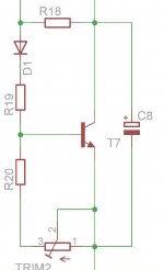
Some small changes like one layout has the zeners at the front and I added two trimmer so I can adjust the offset.
Greetings Gabor
Attachments
-
 355017d1371576132-my-first-diy-amplifier-20-years-go-gaborela-my-first-diy-schem.gif46.8 KB · Views: 487
 -
 355016d1371576132-my-first-diy-amplifier-20-years-go-gaborela-my-first-diy 1.GIF21.7 KB · Views: 472
 -
 355016d1371576132-my-first-diy-amplifier-20-years-go-gaborela-my-first-diy 1 with diode.GIF21.7 KB · Views: 420
 -
 355016d1371576132-my-first-diy-amplifier-20-years-go-gaborela-my-first-diy mode.GIF44.2 KB · Views: 442
Member
Joined 2009
Paid Member
I suggest upgrading the Vbe multiplier using the Hagerman version - see my TGM5 thread.
Bigun your advise to use these type of VBE?
These from your TMG5.
I want to increase the stability of the amplifier by any mean as long as that does not degrade the sound badly.
Greetings Gabor
Attachments
looks very nice!
do you need pot for dc offset ?
and I guess easy to add pcb mounting holes.
I am v interested to hear you impressions of different Darlington devices.
Yes I will use holes to mount the transistors.
I can get read of the trimmers or only use one, the problem the huge beta difference between the MJE243/253 somehow I have to compensate otherwise I end up with offset..
I want to use these complementary for VAS I do like them a lot.
Other option I have to select the signal transistors to get read of the offset or increase/decrease the voltage on the signal transistor selecting the right value resistor..
I know only one trimmer would do the job.
What is your advise, some simple solution?
After set up I can replace the trimmer with the right value resistor and use jumper on the trimmer place.
These for board evaluation.
Greetings
Attachments
I made some basic mode
Someone advised (I think Asok) to change the VBE from PNP to NPN, I don't think that would give more stability but let try it, so BD139 instead BD136.
Also I added a 100N capacitor across on the VBE.
The basic problem here I do not own a scope so I have to be very careful to do bigger mods.
I do not want to invest into scope, can not do DIY all my life, 
Here is the two schematics one with the NPN type of VBE.
If you guys think these better I will mode the layout to.
Greetings Gabor
Someone advised (I think Asok) to change the VBE from PNP to NPN, I don't think that would give more stability but let try it, so BD139 instead BD136.
Also I added a 100N capacitor across on the VBE.
The basic problem here I do not own a scope so I have to be very careful to do bigger mods.
I do not want to invest into scope, can not do DIY all my life,
Here is the two schematics one with the NPN type of VBE.
If you guys think these better I will mode the layout to.
Greetings Gabor
Attachments
Member
Joined 2009
Paid Member
Bigun your advise to use these type of VBE?
These from your TMG5.
I want to increase the stability of the amplifier by any mean as long as that does not degrade the sound badly.
Greetings Gabor
This type of Vbe is no better or worse in terms of sound but it is more stable with changes in Vas current. Do look at the TGM5 thread for the link to Hagerman website as it gives more information, perhaps an even better version. I remember that you can optimize the performance of the version I used by adjusting the resistor (R18 in my TGM5 that you showed) so that it keeps stable bias in your particular circuit, which may require some trial and error. The emitter degeneration of the Vas devices also helps to reduce Vas current variation with temperature, with higher values are more stable but distortion is higher because it reduces open loop gain. I think it is good to start with the values you have chosen and try maybe 1k only if you need to. Use a good size heatsink for the output power device adds further safety and put Vbe device onto the Darlington power device instead of the heatsink also gives better thermal feedback without lag from thermal capacity of the heatsink.
I can think of no significant benefit from changing Vbe between pnp or npn but for some implementation it is beter to use high beta device because base current is smaller. I am not sure if it is a significant factor if using the superior Hagerman design. Do use the Hagerman (he has good information on his website).
Perhaps for offset adjustment R3 could be a trimmer ?
Make C9 and C10 as large as possible, they carry speaker return current so are v important. C7 and C8 can be smaller and rail resistors can be a bit larger ?
Last edited:
Thanks Bigun
These is Hugh opinion about these VBE mult.
I will try to figure out something, I do not accept that is not possible to achieve better stability.
By the way the BD139 at the schematic (the symbol of the transistor is reversed) it shows wrong polarity.
My mistake. I will fix it.
I will try to adopt your VBE with a high beta transistor or may be I use a darlington there to.
Yes I will remove it from the main heat sink, but with these PC board I can not month on the to of the power transistor
because the layout..
AKSA Australia
diyAudio Member
Join Date: Sep 2001
Location: Melbourne, Australia Default Vbe Multiplier Circuit
--------------------------------------------------------------------------------
Paul,
I have seen this circuit and studied the explanation.
It is based on the industrial need for a consistent collector/emitter voltage across a range of currents, a situation which does not normally prevail in the biasing chain of a PP SS amplifier since the current through the voltage amplifier is close to constant, or at least, plus and minus about 10% (yea verily, even with a bootstrap!!).
In audio amps the Vbe multiplier contends with only minor current variation, but must compensate with considerable accuracy for temperature variation in the output stage. Base/emitter voltages in output and driver devices change widely over the temperature operating range, and this has profound effect on bias stability unless the Vbe multiplier is thermally coupled to and thus tracks this temperature. Bias stability is important in Class AB amps because it strongly influences the sonics and keeps the amp operating safely.
Thus the lengths Hagerman goes to are not strictly required in audio, but I suspect in industrial instrumentation this feature might be very useful.
Cheers,
Hugh
Attachments

Last edited:
Member
Joined 2009
Paid Member
These is Hugh opinion about these VBE mult.
Hugh doesn't use push pull Vas so his comments do not apply to your design, which has inherently less stable current through the Vas.
If you can not put the Vbe onto the power device then you have to keep it on the heatsink unless you sandwich the Vbe between the pcb and power device like I did on the TGm7 and the TGM8 but why not keep it on the heatsink for now.
Last edited:
.....Someone advised (I think Asok) to change the VBE from PNP to NPN, I don't think that would give more stability but let try it......
Hmm.... ! I don't remember saying that PNP is more stable but I do remember saying that I used an extra resistor in the Vbe multiplier which appeared to be stable in my test circuit ( not simulation!). I will find that post again! Maybe I used a PNP there. I don't remember. Will get back after checking what I did on that board.
Cheers.
OK, I found the post about NPN and PNP bias spreader.
" Originally Posted by wahab (Post 3531435)
.........it appear that in the original design a PNP VBE multiplier
was used because it has lower junction voltage and as such
it seems the Iq is slightly more stable than with a NPN .......
.."
The one about using a resistor in the bias spreader is here:
http://www.diyaudio.com/forums/soli...diy-amplifier-20-years-go-45.html#post3581134
Hmm.... ! I don't remember saying that PNP is more stable but I do remember saying that I used an extra resistor in the Vbe multiplier which appeared to be stable in my test circuit ( not simulation!). I will find that post again! Maybe I used a PNP there. I don't remember. Will get back after checking what I did on that board.
Cheers.
I do remembered wrong, sorry about that ashok!
Here is the silkscreen with the pars on it. I did include Wahab mode on the front!
Bigun I left out one of the trimmer and the other side the extra resistor, I hope like these I can adjust the offset..
I will mode the VBE - will test something similar to yours
The funny thing with LatFet the amp rock stable, adding extra 4 diode with Toshiba 2SK1530 & 2SJ201 also fine.
These will be a test board , want to test some Sanken and other darlingtons to.
I ordered some clad board from epay, I hope arrive soon so I can start it
Greetings
Attachments
Bigun
Here is the VBE U advised , from your TMG5
Those red are the new values plus the 47R extra resistor!
What do you think, can I test it how is it
If is OK just need the values to be adjusted I will mode the layout....
I will look for darlington transistor in the same package like the BD139, so I use faster device..
Greetings
Attachments
Last edited:
Hello
Bigun or anybody expert would you please take a look at the schematics and let me know which VBE solution is better
There is a small difference how the 47R connected
At the schematic already posted the 47R is in series with the 100R to the base of the darlington.
I see you connected the same way at your TMG5
I just realised that I moved it so only effect the VBE transistor collector.
Would you be so kind and take a look so I can mode the lay out.
Of course the 1K resistor value must be adjusted in real life, before it was 2.2K, if I remember well you wrote at least start with 1K.
Thank you
Greetings
Attachments
the 47r is used by D.Self.
He and Feucht describe how it works.
You will have to adjust the 47r to suit the VAS current you plan to use.
expect a much lower value 12r to 22r usually covers the range of VAS currents found in most amplifiers.
You could assemble the Vbe on a plugboard and apply a fixed current from an adjustable CCS. plot the Vbe voltage against current. See plot in D.Self's book and website.
Hello
Thank you Andrew. I think for start I will pick a 22R resistor. Also the 33uF capacitor may be to high.
Almost I needed need to redesigned all the layout because I replaced the Vbe PNP to NPN type.
Same time I removed the power transistors from under the PC board so I can month the VBE on the top of the darlington (not direct to the heatsink)
I just finished
I purchased some clad board from ebay (so expensive at the local store) when it arrives I will do one board and test it.
If it works out the stability fine finally I can build it.
I do love these little amp a lot.
Greetings Gabor
Attachments
- Home
- Amplifiers
- Solid State
- My first DIY amplifier 20 years a go