The main reason I asked you to mount the 2 power BJT and heat sensor on one heatsink that will give you offset stability!
Those must be thermal coupled (connected)..
The size of your heatsink is another thing.
Did you try different value feedback resisters or just the 6.8K?
If yes what is your experience, how much influence has on the sound?
Probably U use only a few mA bias that is why your amp remain "cold".
Can you let us know your total bias/channel when you start up the amp and after an hour listening at normal level.
Thank you
Greetings G
I'm going back to the Darlington setup to study the bias issues and also to see if the sound is any different. I'm not worried about small changes which could be influenced by many factors. Mainly looking for difference in bass performance. I think the LatFET HF has a bit more attack in the right way.
Will also try out the bipolar assisted scheme that I've been using right now.
Current pcb has already been chopped up in a few places !
The last check will be the 2SB/2SD drivers. After that I'm going to make a one board stereo amp. I have a large enough heat sink which I will have to anodize black.
Haven't seen anyone reporting on some exploratory work yet !")
Will also try out the bipolar assisted scheme that I've been using right now.
Current pcb has already been chopped up in a few places !
The last check will be the 2SB/2SD drivers. After that I'm going to make a one board stereo amp. I have a large enough heat sink which I will have to anodize black.
Haven't seen anyone reporting on some exploratory work yet !
I just wrote to borys, he designed the VAAS with BJT and hexfet.
I want to know if he has any bisa issue when he uses bipolars.
in these page you can find the schematic
http://www.diyaudio.com/forums/solid-state/237219-fet-hex-explendit-amplifier-6.html
To me to do any exploratory work I would need a scope, sim software and some other tools.
I did what I could without those tools over the years..
Actually I'm more than satisfied with the sound of the amp I get with the provided transistor set and other parts I use right now.
If the amp would be more stable that would be an extra but again I do live the sound so much even with the bias issue I will use it.
Of course I will test it with the LatFet maybe with Toshiba 2SK1530/2SJ201 to.
In case I can achieve the same sound quality I will switch to the power FET. Otherwise I will build the amp as solid as possible so even with these bias drifting the heatsink and power transistors can handle the extra heat..
After two and half decade it would be time to settle done with one or two system and enjoy listening to music.
Ashok you have scope, can you please check if the amp has any oscillation with the darlingtons.
Of course after you return to the darlingtons.
Can you keep one channel with the best performance you get and use another PC board for A-B test.
That way you can avoid any mind tricks etc.
Also please take a look at borys schematic if we can use some of his idea here.
To me to do that I would need to invest into scope etc or go back time to time to the TV shop I used to help. The owner has all the tools I would need.
I do not have time for hat
Thanks for your work on these project.
Greetings G
If you have BDX I think that is good enough. Or BDW93C & 94C those are also in TO220 case.
To be honest I really do not understand why we should use darlington for bias spreader..
But we have nothing to lose if we test it.
If you read borys answer to my question about how stable the bias he mentioned also it has some drifting.
Now if we bias the darlington only up to 50mA or less we get also les bias drifting.
For years I didn't realised the amp has these issue because of the low bias set up!
I will follow that thread to see what happened if someone will use darlingtons or some other guy build the amp with any type of BJT.
It would be great to get more feedback on that.
Greetings
Hi G,
At least you know the LatFET works fine and has stable bias AND sounds very good. I feel reluctant to disconnect it and put back the Darlingtons.
This time the bias circuit is going to be outboard so that I can try out variations. Yes, I'm going to make one more board ! I have an extra heatsink with the same size. The IRF240/9240's are also beckoning me ! Better I use them or blow them . Otherwise they might stay in the box for another 20 years !
QUOTE=djk;3545045]The close-spaced fins will do little of nothing without a fan.[/QUOTE]
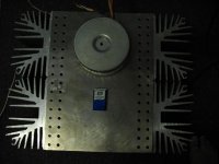
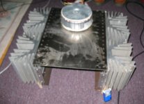
If the heatsink will be not efficient enough I will ad 2PC 4" fan connected in series under the heatsink.. That would handle a Class A 30W amplifier with the fans.
Before I used the black heatsink mounted on each side now (I cut those two 2 piece) easily handled 150mA at 40V rail voltage.
The heatsink after few hours was only 40C degree so I increased the bias to 250mA .
After listening two CD I felt seep and I blew up the amp several hours latter.
Look at the picture..
I woke up at the middle of the night the amp was on fire. The CRC 10W resistor was hot red.
On the PC board burnt a hole.
Thank God my Visaton handle the 40VDC.
Next time I'll be more careful.
In case you think the heatsink still not enough efficient I can use these amp case I just work on it.
It is about 50LB or more.
Just kidding. That for a F5T with Toshiba mosfets or high power Krell KSA50..
I worked on these case all week but now I have to start to test these amp and the Hitachi LatFet amplifier to.
Time to do some test to improve the amp stability..
boyet0173 how is going? Any improvement..
Greetings Gabor
If the heatsink will be not efficient enough I will ad 2PC 4" fan connected in series under the heatsink.. That would handle a Class A 30W amplifier with the fans.
Before I used the black heatsink mounted on each side now (I cut those two 2 piece) easily handled 150mA at 40V rail voltage.
The heatsink after few hours was only 40C degree so I increased the bias to 250mA .
After listening two CD I felt seep and I blew up the amp several hours latter.
Look at the picture..
I woke up at the middle of the night the amp was on fire. The CRC 10W resistor was hot red.
On the PC board burnt a hole.
Thank God my Visaton handle the 40VDC.
Next time I'll be more careful.
In case you think the heatsink still not enough efficient I can use these amp case I just work on it.
It is about 50LB or more.
Just kidding.
That for a F5T with Toshiba mosfets or high power Krell KSA50..I worked on these case all week but now I have to start to test these amp and the Hitachi LatFet amplifier to.
Time to do some test to improve the amp stability..
boyet0173 how is going? Any improvement..
Greetings Gabor
Attachments
I think the thermal stability should be fixed. Having a very large heat sink might help but isn't a good idea. I really haven't been looking at the problem closely. We've all been attacking the problem casually !
My out of town trip starts on Tuesday and from then onward I'm going to be really busy for several weeks. Maybe I can think things through during the trip.
My out of town trip starts on Tuesday and from then onward I'm going to be really busy for several weeks. Maybe I can think things through during the trip.
This is where close rated fusing shows it's hand........... the amp was on fire. The CRC 10W resistor was hot red.
On the PC board burnt a hole.
I only use fuse on the AC..
May be the fuse was a bit over rated.
All together is my fault, we can not set up the bias to 250mA leave the amp on and fall asleep.
ashok
you right about the heatsink, but in my case clearly it was undersized for the 250mA bias
My friend used the amp more than 9 years until one channel started to distort for some reason.
He biased the amp over 300mA but he used huge heatsink, lower rail voltage and regulated PS.
I do not think the regulated PS has anything to do with the stability.
Much more the size of his heatsink and lower rail voltage.
Again the Mosnter Hiraga acted the same way or worst to me, when I started up it had 0.8A bias after warm up it had 1.5A and I run the amp 12V rail voltage.
These amplifier has much less bias drifting, sound much much better..
Thousands built the Hiraga Monster even do it has that issue.
Of course I'm interested to somehow make the amp more stable, in case we can't succeed.
If not I still need these amp because I do love the sound of the amp a lot.
I believe the best I ever built with the mentioned parts.
Greetings.
Do you remember me mentioning that the same amp was stable when it had a slow stream of air blowing across the heat sink. So the alternative to a large heat sink is a smaller heat sink with fan. But then one has to study it carefully. I had it working like that about 3 to 4 hours. The solution would be a combination of the thermal resistance of the system with or without fan and an optimum thermal solution for the bias spreader transistor. Need time to do that ! Maybe we need more than 24 hours a day ! ( feasible on another planet I guess !)
That is not a "fault"........All together is my fault, we can not set up the bias to 250mA leave the amp on and fall asleep.........
Equipment designed to safely operate for year after year should never catch fire because it has been left ON all night.
It should operate just as well after 7days of continuous running as it does after 7hours of continuous running.
If you have an amplifier that consumes 50W from your 110/120Vac supply then using a T5A fuse in the mains supply is virtually guaranteeing continued operation for a LONG time after a fault has developed.
Whereas using a T1.6A for a 200VA transformer running on 110/120Vac will likely blow quite quickly if a serious fault occurs.
Last edited:
In my case I had a 1 watt 10 ohm resistor in the fuse holder on each rail. However the power transistors were still dead !
The resistors burst into flames and it took me several moments to get up and reach the power switch. The ( loud) music had stopped some time before that and there was nothing playing but the bias current must have been building up slowly. Never had a breakdown after that as I kept the bias lower than 80 mA.
I'm itching to try out the pnp bias spreader and the Darlington one but I have no time. I'm off in a few hours and will be gone for a few days.
That is not a "fault".
Equipment designed to safely operate for year after year should never catch fire because it has been left ON all night.
It should operate just as well after 7days of continuous running as it does after 7hours of continuous running.
Andrew
I agree with you 100%
Please understand me, may be I was not clear enough.
I made several test on the amplifier, I tested different components.
I set up the bias 150mA and it work fine for several hours, I check the heatsink and was cold around 40C degree.
So I increased the bias up to 250mA and kept listening music until I felt sleep.
Now when I increased the bias by an extra 100mA I supposed to wait until the amplifier totally warm up and settle done!
That is why I wrote "it was my fault"
When I felt sleepy I supposed to shut of the amplifier! We can not set up a amplifier and leave it unattended.
Several years back with 3 pair power transistor, 18VAC transformer and huge heatsink I biased the amplifier to 3A.
Day after day I left the amp on with out any problem.
Again for that 3A bias I used the right rail voltage, and more than enough heatsink!
I think 90% of the amplifiers would have thermal runaway if the heatsink does not handle the heat or the power transistors is pushed over the limit.
If we have protection so the amp shut off in case if over heat that is another think.
I hope you agree with these.
In my case the amplifier was under test, it was not a finished amplifier!
Back in Europe I used the amplifier for a while with out any problem.
Of course when I immigrated to Canada I didn't brought with me.
Now after 15+ years later those transistors I used no longer available.
My friend also built these amplifier and more than 9 years had no issue with.
There is a Hungarian corp. who built commercial amplifiers to the market based on a very SIMILAR circuit.
Our problem when we build a amplifier even if it sound great we want to get better result.
So we start to switch components, looking for the sweet spot.
Many of us who used to it to Class A amplifier circuit we right away play with the bias to.
Yes the sound get better by increasing the bias but we must play safe!!!
I think I made a mistake I posted that picture because sometimes people does not read the comment and now they think better not to do anything with these circuit or these amplifier
I can assure you with 35V rail voltage 50mA bias with the right size heatsink the amp will operate years and years.
Greetings
I'm back but will be here only for 5 days.
Hi B.
Is the circuit shown at http://www.diyaudio.com/forums/solid-state/237219-fet-hex-explendit-amplifier-13.html#post3557637
enough to satisfy you that the discrete Darlington also works well ? ( post 123)
Cheers.
Hi B.
Is the circuit shown at http://www.diyaudio.com/forums/solid-state/237219-fet-hex-explendit-amplifier-13.html#post3557637
enough to satisfy you that the discrete Darlington also works well ? ( post 123)
Cheers.
Hello
Yes it does work I knew that, I tested way back 15 years ago.
There are several question
First of all the sound, we have to wait until someone build it and will compare with an acceptable amplifier.
Don't forget I built the amp with discrete darlington and it was only the shadow of the darlington but I didn't used Sanken BJT.
It can be because I used wrong transistor set up, who knows.
There is a similar amplifier called Canopus with discrete darlingtons but the sound of that amp not the same league, not even come close to these.
Second borys at the test he set up the bias around 60mA and when the amp warmed up it was the bias went up around 90mA or so.
He wrote the amp was after stable.
My amp is stable with low bias like that with proper size heatsink.
Also he wrote that little bias drift probably it happened because the heatsink compound was already dry..
Who knows??
I wish the discrate amp would be rock stable and the sound compare to the darlington at least the same level or so.
I sent my darlington circuit to borys, he asked me so he can see it.
He is on vacation for 2 weeks but until that he wrote to try the amp out with darlington heat spreader BD682 or other type
Also he wrote the 2SA1360/2SC3423 is not the best only linear until 20mA..
Al do right now I use the MJE243/253 set for VAS, I mentioned to borys but he forget that.
At the schematic I had the 2SA1360/2SC3423 , which was advised by wahab.
Borys wrote to try out the Toshiba 2sc4793 2SA1837 which I have at home.
I will do these tests soon.
The good news someone will build borys amp soon and will compare it with the LC LatFet version.
So hardly wait to get some info about the discrete darlington.
Otherwise I do not worried at all because my friend used these amp more than 9 years over 300mA bias.
I will use large heatsink, also I will test some other power darlingtons to, and let see if some of the borys idea will make the amp more stable.
These amplifier sing good at 150mA bias but over 250mA much better according to my friend and my ear to.
The reason I force the higher bias not only 50mA.
Another think the amplifier very sensitive to the components used in the circuit.
So carefully selected components will help to get closer to Nirvana...
My last setup was very-very good. The very best sound in my system.
The biggest help it would be if someone could run some sim. tests.
Since I do not own scope without sim I have no clue if the amp oscillate or not with the new transistors.
Greetings G
I see a lot of people have interest in this amp but only a few seem to be reporting the progress. Maybe the others have not built it yet. There are so many designs on this forum. Must be truly confusing when it comes to picking a design to try out !
Well I'm off again for a week by the beach ! And soon after I get back I will be off again to another beach !
Meantime hope someone will check out the bias stability with the bias transistor fitted close to the power transistors. I felt that maybe we can use a power transistor itself ! It's got a much larger metal tab and so might have better heat sensitivity in this application. Maybe it's the time lag that's the biggest culprit in this case.
I found TTC5200 and TTA1943 in the market. Got a few to try out. I thought it was made in China but the printing says Japan !
I'm back for a few days.
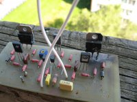
I placed the bias spreader transistor right next to the Darlington power transistor. I raised the bias till the heat sink got quite warm and bias level was about 180 mA. This took about 20 minutes. Then I dropped the bias down to 100 mA and it has been fairly stable for the last 20 minutes. Ambient is 29 deg C and no air flow around the heat sink. The heat sink is vertical and so vertical air flow is free. Even the slightest external flow of air drops the bias levels.
So I guess with a bigger heatsink all will be well for the bipolar implementation. With a fan there will be no problem at all with smaller heat sinks but unsafe in case the fan breaks down. I noticed that my heatsink is 'at least' 1/2 the size that some others have been using on a similar amp.
So now on to the next step. Have to get the changes completed in less than 2 weeks . Anyone completed the amp on a larger heat sink ?
Would it be worthwhile to incorporate the relay speaker protection on board ? I have it now on a separate board which contains the psu.
Last edited:
- Home
- Amplifiers
- Solid State
- My first DIY amplifier 20 years a go