Just powered up the Bipolar assisted output stage ( LatFET).
Everything sounds the same as before but the bipolar's do get slightly warm at high volume. Without a careful listen I can't say if anything got better or worse. If anything bass is tight and deep and treble quality has not changed. I used to think that bass was slightly less damped with the LatFET alone but then I could be wrong .
I find that voice still sounds the same and has not deteriorated in any way. I need to check closely at the point when the bipolar's kick in. Problem is that it's pretty loud by that time ! Hope my neighbours don't complain.
Bottom line is that I didn't loose anything that is glaringly noticeable. So now on to the stereo version and see what we get there.
Maybe the new board should be easily switchable between LatFET and bipolar ( while assembling!). I'm targeting about +/-56V supplies.
Maybe distortion tests will throw up some interesting details ! Have to find my dummy 8/4 ohm load.
Yeah I'm pretty much aware of the NFB caps and it's value. I didn't want to go larger as I don't have better types of that size. In any case it is good enough as it is. Bass is good right now. It won't audibly go any lower if the LF -3dB point goes any lower. Right now that is at about 1 Hz ! I do use low voltage caps ( 16 V ). This cap only sees the base emitter voltage plus the drop on the emitter resistor which adds up ,in my case, to under 1 volt.
The current heat sink seems pretty good with the LatFET's. I'm playing pretty loud and it's not getting too hot.
I don't expect the bipolar add-on version to tighten up the bass as it comes on only at higher voltage levels . So if the speakers back emf is the controlling factor , those bipolar's probably won't do anything for it.
I've always been curious about how it would sound and right now it's easy to rig it up. So before everything is stripped up again , it's time to make a test.
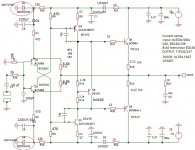
About stability. I have not used C6 and C7 as shown. I've used base collector caps of 47pF on the two drivers and everything is fine.
With the LatFET I decided to try the C6 and C7 as shown on your circuit and it oscillated badly. I've used 220 ohms at the gate.
Funny thing when I made the layout I do had the feeling we will need (Miller caps on the drivers with the LatFet) so I made room for that on my layout.
I do not own a scope so to avoid oscillation better to have them.
Good to know we may need them...
I don't expect the bipolar add-on version to tighten up the bass as it comes on only at higher voltage levels.
The main reason I do not want to give up the darlington power transistors.
I don't think you will get any benefit out using bipolars on LatFet at least not sound wise.
It may add some fullness to the bass (not even sure about that) but please pay att. the bass not to become muddy and rounded..
Same thing when we increase the caps value on the feedback.
I don't think it will go deeper or tight up the bass just by increasing the size of the caps.
But again if the capacitors are under sized that bad to...
Probably better quality caps like Nichicon Gold 470uF would do the job.
Same true on the input caps. You have to find the right quality and right value..
Very important to do A-B test after any mode, otherwise you will get lost.
Even at A-B test the new parts can play trick on us (new parts most of the time need some burn in time)

If you have different driver transistors please test those.
You may get surprised.
That gave me a huge sound improvement. I did tested at least 7 or 8 type transistors for driver and still has some others to test them.
I read the same some other simple project like P3A the right driver transistor is a big factor according to Sakis..
Be careful when you increase the rail voltage, if you blow up the mosfet that will take your expensive speaker to.
Please keep inform us with your progress.
Thank you
Wahab a big thank you for the sim. and for your help!!!
Greetings G
Attachments
Member
Joined 2009
Paid Member
Hi Ashok,
I also looked at the use of an extra device connected across a resistor in series with the collector of the output Darlington in simulations last week - same idea as yours but with the Darlington instead of the FET. I wanted to see how I could use two pairs of Darlingtons without having to match them. I tried a few combinations - there's even a non-swtiching output you can make. But I found an increase in 5th harmonic and others whenever the extra device becomes actrive. It will be interesting to learn what you find from the listening tests.
I also looked at the use of an extra device connected across a resistor in series with the collector of the output Darlington in simulations last week - same idea as yours but with the Darlington instead of the FET. I wanted to see how I could use two pairs of Darlingtons without having to match them. I tried a few combinations - there's even a non-swtiching output you can make. But I found an increase in 5th harmonic and others whenever the extra device becomes actrive. It will be interesting to learn what you find from the listening tests.
I'm back again after a busy and tiring afternoon.
First thing done after entering the house was to turn on the amp and play 'Sade' ( Love Deluxe).... Sounds VERY nice ! Deep and tight bass . Strangely the bass appears tighter than before the bipolar was added. This must be the mind playing tricks ?
I wanted to push the amp into clipped mode to see what would happen. In my case the supply is not very stiff so the voltage would drop a lot. True enough I got just about 30 V peak just under clipping. That's about 50 watts into 8 ohms. But then the mains is also very low today...about 200 V instead of 230 V.
The amp sounds quite good even with the bass clipped very often. BUT there has to be a problem ....so says Murphy..and so there was ! Every once in a while there was a low level spitting noise from the tweeter ! There was a short burst of RF oscillation on the music signal at that point. Can't say at exactly what level it happened but I'll test it out with burst signals at different frequencies and see what I find. But it only happens when driven very hard and not very often. Have to fix it of course before making any other pcb.
But I am quite happy because at most listening levels it sounds quite good. I didn't try to sim this as I don't have all the spice models.
Bigun: A Darlington on the output is an over kill because the first Darlington can very easily drive an ordinary bipolar power device. Besides that the 2nd Darlington eats up more Vbe. It's min Vce will be higher and it will get hotter. This also depends on if you connect the collector to the output or to the first Darlington's emitter resistor.
As far as simulated harmonics go , when the levels shown are low it's always best to build and listen to it.
Higher voltages are always dicey as failure can be quite spectacular !
My speaker goes through a relay protection circuit that protects against dc faults. So amp failure should not create any problems unless I get RF that burns out my tweeters ! The scope is on most times so hopefully I will see that happening and stop it on time.
If all goes well I'll double the add on bipolar devices and raise the voltage. I happen to have 2SB649A and 2SD669A . While I have MJE340/350 and BD139/140 I think they would be a step down in performance. My bipolar output power devices are Fairchild 2SC5200/2SA1943 . I also have original Toshiba 2SC3281 and 2SA1302 . This was bought a long time ago ( 1996).
I guess the IRFP240/IRFP9240 are not worth trying in the place of the LatFET's. They are just a different ball game and I feel maybe a step back. Don't really have time to test all the permutations and combinations.
Now I have plenty of work to get done , so no more testing tonight.
It would be great to test the 2SB649A and 2SD669A I also has 10 pair.
I did tested the BDs they blew up around 40V rail voltage.
Also tested the MJE340 & MJE350 I don't like those.
Do not even try MJE150## in case if you have some, I tested those to NO for these project.
Good to know you have speaker protection, I got several time 40VDC on my Visaton woofers because blew up power stage..
Someone already started a project with the mentioned Hexfet to..
Greetings Gabor
Hi G,
Was just about to shut down the computer when I saw your message.
I'll try the 2SB/SD. Remember we have not yet tried out 2SC2240/2SA970 . I also have 2SC1775/2SA872 ! Then there is the 2SK246/2SJ103 . Unfortunately I don't have 2SJ74 at the moment.....If only we could extend the number of hours in a day by say 4 more hours....we could have done lots more in a day !
Is that a very .....thought ?
Was just about to shut down the computer when I saw your message.
I'll try the 2SB/SD. Remember we have not yet tried out 2SC2240/2SA970 . I also have 2SC1775/2SA872 ! Then there is the 2SK246/2SJ103 . Unfortunately I don't have 2SJ74 at the moment.....If only we could extend the number of hours in a day by say 4 more hours....we could have done lots more in a day !
Is that a very ..
...thought ?Member
Joined 2009
Paid Member
this could well be real, distortion on bass transient should be betterStrangely the bass appears tighter than before the bipolar was added.
Bigun: A Darlington on the output is an over kill because the first Darlington can very easily drive an ordinary bipolar power device. Besides that the 2nd Darlington eats up more Vbe. It's min Vce will be higher and it will get hotter. This also depends on if you connect the collector to the output or to the first Darlington's emitter resistor.
Quite right, I wouldn't have considered it if if hasn't got these Darlingtons already bolted to the heatsink.
It seems that you are finding the Latfet version to be as good or better than the BJT and thermal management being so much easier is this your preference so far with your experiments or is it too early to say ?
....It seems that you are finding the Latfet version to be as good or better than the BJT and thermal management being so much easier is this your preference so far with your experiments or is it too early to say ?........
You are correct in judging my preference so far. Yes thermal issues are solved using the LatFET . Darlington's did sound very good but I was worried about bias stability . It appeared to wander too much. It's possible that I did something incorrect that I didn't notice at the time.( like not checking for small occasional RF bursts !...)
If I just had to finalise the designs I'd stick to the LatFET. But I want to go back to the Darlington's once again . IF my 'fresher' memory says that it may sound a shade better I will build two stereo boards one with LatFET's and the other with the Darlington's and compare them properly.
Refining the circuit further will require adding more parts and I want to try and keep that to a minimum. Funnily I assembled a LM4780 recently . I had a chip from long ago and came across a low cost board on eBay. So I decided to use it instead of just wasting it. Will be interesting to listen to it. Will do so this week.
Suddenly there are tons of things to get done before I go out of town for a few days.
....... Someone already started a project with the mentioned Hexfet to......
Yes I came across that. He also said that the bass appeared different. I'm guessing it was lighter sounding and less well controlled ......? Besides the N/P channel versions of the IRF devices are much less matched than the LatFET's. Not that the LatFET's are so great in that regard. But there is no doubt that the IRF devices are much cheaper and more easily available.
Actually I do have a few pairs and maybe I should try it too since I already have a board and the pins are the right way round !
The Renesas web site says that the LatFET's are in full production . Wonder why we do not see the devices easily in the retail market. Are they sold only to OEM's ?
Yes Renesans is still available but I do not like them.
Compare to the good old Hitachi they are no longer the same quality.
These not just my opinion (I did some A-B test) many other users wrote the same.
May be for that reason no longer so popular like was when Hitachi produce them.
I built some Pass amplifier using hexfet. According to Mr. Pass and many other who used hexfet need high bias to give you good performance.
I never used hexfet in Class A-B circuit ....
Even under class A bias it has a bit week bass.
They just came up with a bipolar circuit to. I will follow that thread to see if their BJT version will be stable all do they use les than 50mA bias. At that bias the darlington stable enough to.
It would be good if you could do some measurement on the darlington device if is oscillate etc.
I blew up many BDW93D & 94D darlington produced by ISC even with low bias, after a few minutes, not even warm up.
Probably it oscillated or just junk device, who knows.....
Funny think after I switched to BDW93C & 94C (about half the power ) and those newer blew up even under 100mA bias at 40V rail voltage.
One think is sure I do not give up on these amp with the power darlingtons.
Even if I have to use large size heatsink like Class A amps.
I double up the darlington and let the bias move up and done. My friend used the amp with one pair darlington over 9 years with high 300mA bias..
Actually the Monster Hiraga has the same bias drifting issue, I set up the bias 800-900mA and after warm up I get 1.5A. The reason it cause less problem because it run only on 12V rail voltage..
I need that sound I got from these amp.
Greetings
Hi gaborbela,
I following this thread, I've been test it. I like the sound and almost the same with vssa. my problem is thermal stability. I've experiment also using vssa schematic value and your's schematic and some modes, the results sound great. Sounds very clear and bass is there. I like the sound of darlington over lafet. I even used very small heatsink in normal listening. I used +32v-32v 1 4700uf per rail. I even used also +12v-12v with very good sonic result. I agree to you that darlington has a good bass. So far for now of my experience, this is a very good i've ever built amp.
Regards,
Boyet
Member
Joined 2009
Paid Member
I don't know if you don't like my solution for bias - I did mention it earlier. I built my own version of the VSSA (called TGM5 - a thread here somewhere) with fast Toshiba BJT outputs. Bias was rock solid. The solution I used was to use generous emitter degeneration on the VAS (what I used was too high, I would suggest less but I haven't experimented with the value, I also want to try a bypass cap on the emitter resistor) and I used a bias spreader with better tolerance to variations in the VAS standing current - a design from Hagerman.
It is extra trouble though and I suspect that good LATFETs are the best option overall.
Still, when I get back from holiday (I'm cooling off in Hong Kong today, boy is it hot) I may have to build Gabors circuit with Darlingtons, otherwise how will I know for myself how it sounds ?
It is extra trouble though and I suspect that good LATFETs are the best option overall.
Still, when I get back from holiday (I'm cooling off in Hong Kong today, boy is it hot) I may have to build Gabors circuit with Darlingtons, otherwise how will I know for myself how it sounds ?
Hi gaborbela,
I following this thread, I've been test it. I like the sound and almost the same with vssa. my problem is thermal stability. I've experiment also using vssa schematic value and your's schematic and some modes, the results sound great. Sounds very clear and bass is there. I like the sound of darlington over lafet. I even used very small heatsink in normal listening. I used +32v-32v 1 4700uf per rail. I even used also +12v-12v with very good sonic result. I agree to you that darlington has a good bass. So far for now of my experience, this is a very good i've ever built amp.
Regards,
Boyet
Happy to read another build with good sonic result.
If you have time please post your transistors list and other parts U use so we can see what kind of modification you made..
If you could use a bit more caps in your PS and make it CRC that would be better..
4700uF a bit to low.
Sometimes we forget these amplifier at 35-40V rail voltage produce over 60W or so..
Adequate heatsink must!
Also I would like to ask Bigun, Ashok when you came up with an idea and you have time please make a sketch that way easier to follow, to understand.
To be honest many people does not take the time to read all posts.
I do read every post here because I started the tread.
The same time I follow some other project with same topology, to be honest I do not read each post.
Simple reason I do not have enough time to do so but when I se a circuit, a picture etc I do take a look..
I think we would have more comments, idea etc. if we would post more sketch, pictures etc...
Of course only if and when you have time!!!
Thank you
Greetings G
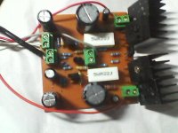
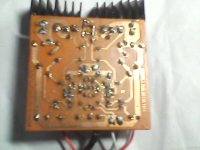
Hi gaborbela,
Here my current setup. If you want you can try this. Now beautifully singing even with small heatsink. Sorry for pics is not clear.
This topology based on your schema Gaborbela,LC and shaan. I want to thanks to DACZ for PCB designed for me..Regards,
Boyet
Attachments
Why is D1 & 2 UF as described on schematic?
If the output pulls the supply low enough that the diode becomes reverse biased, does it matter whether it's a 1N, or UF type?
Hi AndrewT, I used UF because i dont have 1N diode.
Thank you
Some advice
BD136 and your power transistors must be mounted together in one heatsink...
Your heatsink way too small for these project, be careful you can have thermal runaway at any time and that may take out your speakers to!!
To be honest I would be afraid to connect my speaker and play music at any level like that without speakers protection.
Otherwise nice work!
Greetings G
why the noteHi AndrewT, I used UF because i dont have 1N diode.
Diode: ultrafast UF4007
Thank you
Some advice
BD136 and your power transistors must be mounted together in one heatsink...
Your heatsink way too small for these project, be careful you can have thermal runaway at any time and that may take out your speakers to!!
To be honest I would be afraid to connect my speaker and play music at any level like that without speakers protection.
Otherwise nice work!
Greetings G
Thanks for the advise G. But the heatsink is low temperature around 37-40C. I set R15 to 1.3K to make temperature low and R5.R6 47 ohms. And also feedback resistor plays important role in balance temperature both output. That is based on my observation. Any comments are welcome.
why the note
Andrew would a slow diode be better ?
I can't see it matter.
- Home
- Amplifiers
- Solid State
- My first DIY amplifier 20 years a go