Did a quick comparison of this amp with levels matched against another CFB amp and a Creek 5350 amp. This amp sounds better than the other CFB amp but not as good as the Creek. But some aspects of this amp sounds different ( better ?) than the Creek. The Creek had better weight in the bass end. But as I have noticed earlier this difference could be due to the quality of the input coupling capacitor also. Transients seem to have more bite on this amp. The Creek has no input capacitor.
This isn't the end of this test. I will have to try it without an input cap !
Might cause some dc shift in the output. So the conclusion is that more controlled testing is required. Compared to the other CFB amp it appeared to sound louder and more dynamic even though it was level matched. An input cap problem on the other amp ? Interesting situation. I'm going to bed. Has been a long day.
Cheers.
Hello ashok
Safety first!
I worried a bit when you push the amp all the way at 40V rail voltage. Your heatsink way to small, min double req. if you push these amp.") and you need at least 2 pair power transistor. That has to be matched otherwise you invent some problem to.
and you need at least 2 pair power transistor. That has to be matched otherwise you invent some problem to.
Now I don't know how much you want to invest to these project, it is your pocket I can not recommend only can give you some advise or share my experience.
I never used at these project small power supply caps. I used 4PC Mepco 50 000uF CRC set up, and I used Mallory also 4PC 62 000uF. Those are my bench power supply.. I purchased for these project some Super Through 6800uF and Kendeil 50 000uF caps but not tested yet.
Because I built so many amp I did tested many type of capacitor in those PS.
Let s pick something not to expensive but still good quality.
I do like 10 000uF Nippon CC KMH type brown sleeve, Jamicon. These provide great dynamic, punchy, clean sound, good filtering.
I do like also BC Philips, Panasonic also all do they provide softer sound, softer bass but not bad.
Now you can use Nichicon Gold, Elna Lao, Elna for Audio etc but they cost much more.
I would avoid to use regular Nichicon, Rubicon, Samwah etc.
On the PC board I tested many exotic caps.
To me the 10uF Elna Silmic, 220uF or 330uF also Elna Silmic, here you need only 16V...
For 1000uF Nichicon KG Muse (black & gold sleeve not the green) very natural, well balanced, Elna Cerafine, Nichicon Gold good to, Elna Silmic is great but sometimes ad to much color specially in to the bass area.
I would avoid Samwah, I tested in some another project and sound thin, horrible in any way.
Please do not go over 1000uF. I don't like large caps on the PC board.
The 10uF must be close the the power connection and to the power transistors as possible.
That is why my lay out ended up the way it is. Carefully designed..
I didn't find any cheap foil caps I like on the input.. I tested some Wima, Siemens, ERO, etc but I prefer Black Gate Non Polar (red) over all mentioned foil caps.
10uF Elna Cerafine, Nichicon KG or gold, Silmic also great.
Now if you want to spend on exotic foil caps please pick your favorite.
I do read Russian K72-16 great cap and cheap but I newer tested on the input.
The 39pF or what ever U use must be dipped silver mica, that ceramic type way to noisy.
Transistors
BC550C/560C or 2SK170BL/2SJ74 on the input
Drivers
Here I tested a lot of different transistor because originally the circuit was designed with BF469/470. These transistor quality today and 20 years a go like heaven and hell.
Today only can get them from CDIL but again they are horrible.
So I tested ON semi MJE15### types, MJE340/350, Toshiba 2SA & 2SC type several of them, BD139/140 Philips (I blew them up) to high voltage..
Far!!! the best I got MJE243/253. It has in these circuit the most natural, clean, dynamic sound with deep I mean deep bass.
It took the amp to a different league (where it was with a good BF or even get better)
Now the MJE243/253 will cause some offset but you can get read of carefully matched signal transistors or J Fet or by using a trimmer pot there.
For wires I like white 14-16AWG silver teflon not solid core, or 16AWG Cardas hock up wire.
Hard to work with but it has very natural sound, it worth to use it for DC.
You can use 16-18AWG pure silver wire in teflon tube but very expensive.
For signal I only use 30AWG or thinner pure silver wire where no shielded OK.
Please keep as far as possible from the transformer and from PS wires..
Transformer for 2 channel 300VA must, I use 250VA /MONO.
Now again replacing some of the transistors you can end up with a good average sound, still good but far from the best the little amp can provide.
Resistors my favorite and not to expensive PRP or DALE.
The best to upgrade to do always A-B test so keep one channel and upgrade the other.
Greetings G
Safety first!
I worried a bit when you push the amp all the way at 40V rail voltage. Your heatsink way to small, min double req. if you push these amp.
and you need at least 2 pair power transistor. That has to be matched otherwise you invent some problem to.Now I don't know how much you want to invest to these project, it is your pocket I can not recommend only can give you some advise or share my experience.
I never used at these project small power supply caps. I used 4PC Mepco 50 000uF CRC set up, and I used Mallory also 4PC 62 000uF. Those are my bench power supply.. I purchased for these project some Super Through 6800uF and Kendeil 50 000uF caps but not tested yet.
Because I built so many amp I did tested many type of capacitor in those PS.
Let s pick something not to expensive but still good quality.
I do like 10 000uF Nippon CC KMH type brown sleeve, Jamicon. These provide great dynamic, punchy, clean sound, good filtering.
I do like also BC Philips, Panasonic also all do they provide softer sound, softer bass but not bad.
Now you can use Nichicon Gold, Elna Lao, Elna for Audio etc but they cost much more.
I would avoid to use regular Nichicon, Rubicon, Samwah etc.
On the PC board I tested many exotic caps.
To me the 10uF Elna Silmic, 220uF or 330uF also Elna Silmic, here you need only 16V...
For 1000uF Nichicon KG Muse (black & gold sleeve not the green) very natural, well balanced, Elna Cerafine, Nichicon Gold good to, Elna Silmic is great but sometimes ad to much color specially in to the bass area.
I would avoid Samwah, I tested in some another project and sound thin, horrible in any way.
Please do not go over 1000uF. I don't like large caps on the PC board.
The 10uF must be close the the power connection and to the power transistors as possible.
That is why my lay out ended up the way it is. Carefully designed..
I didn't find any cheap foil caps I like on the input.. I tested some Wima, Siemens, ERO, etc but I prefer Black Gate Non Polar (red) over all mentioned foil caps.
10uF Elna Cerafine, Nichicon KG or gold, Silmic also great.
Now if you want to spend on exotic foil caps please pick your favorite.
I do read Russian K72-16 great cap and cheap but I newer tested on the input.
The 39pF or what ever U use must be dipped silver mica, that ceramic type way to noisy.
Transistors
BC550C/560C or 2SK170BL/2SJ74 on the input
Drivers
Here I tested a lot of different transistor because originally the circuit was designed with BF469/470. These transistor quality today and 20 years a go like heaven and hell.
Today only can get them from CDIL but again they are horrible.
So I tested ON semi MJE15### types, MJE340/350, Toshiba 2SA & 2SC type several of them, BD139/140 Philips (I blew them up) to high voltage..
Far!!! the best I got MJE243/253. It has in these circuit the most natural, clean, dynamic sound with deep I mean deep bass.
It took the amp to a different league (where it was with a good BF or even get better)
Now the MJE243/253 will cause some offset but you can get read of carefully matched signal transistors or J Fet or by using a trimmer pot there.
For wires I like white 14-16AWG silver teflon not solid core, or 16AWG Cardas hock up wire.
Hard to work with but it has very natural sound, it worth to use it for DC.
You can use 16-18AWG pure silver wire in teflon tube but very expensive.
For signal I only use 30AWG or thinner pure silver wire where no shielded OK.
Please keep as far as possible from the transformer and from PS wires..
Transformer for 2 channel 300VA must, I use 250VA /MONO.
Now again replacing some of the transistors you can end up with a good average sound, still good but far from the best the little amp can provide.
Resistors my favorite and not to expensive PRP or DALE.
The best to upgrade to do always A-B test so keep one channel and upgrade the other.
Greetings G
the bias adjust resistance must be in the base to emitter link.............Bias transistor question ( Q9). Any special reason for using a PNP instead of a NPN ? I used a NPN ( BD139 ).
The Creek is unlikely to be a DC coupled amplifier............. The Creek had better weight in the bass end. But as I have noticed earlier this difference could be due to the quality of the input coupling capacitor also. ............The Creek has no input capacitor.
............
The bass roll-off in the Creek may be arranged around the NFB DC blocking cap.
This will increase the low bass distortion and give the effect of a weightier bass.
Alternatively, the Rin/Zin of the Creek could be lower, or much lower, than your new amp. This would affect the filter that is created by your source DC blocking capacitor.
I suspect there is a scientific reason for the apparent bass difference and that your comparison is not valid due to unexpected filtering effects.
Member
Joined 2009
Paid Member
............ around the NFB DC blocking cap.
This will increase the low bass distortion and give the effect of a weightier bass................
using the NFB DC blocking capacitor to roll off the bass response will change the distortion profile of the amplifier.I have experienced bass differences between amplifiers with the same values of capacitors etc. At the time I put it down to differences in the harmonic profile. More H2 is more rounded bass, more H3 brings more bite. It's just a subjective guess on my part though.
I think you are right even if your conclusion is based on subjective data.
The Bandwidth of an amplifier should (arguable) be set with passive input filtering.
The NFB DC blocking cap should be sized to ensure it never sees any significant voltage across it. This (probably necessary) near zero voltage across the NFB DC blocking cap, means it CANNOT be used to roll off the bass response.
looks like what I call emitter feedback (curr-fb )
but I have never seen this very type before
something new to me = more interesting
practically all transistors can be upgraded, improved
personally I should start with +-30 Volt
and try to make it work/sound perfectly with one output pair
another thing
these type often benefit much with separate power supply for output stage
and the input/driver part a well regulated own supply
Sorry for this beginner's question. A seperate power supply, do you guys then mean a own transformer, or more like the things that come behind the transformer (like the 4 diodes I Always see)
The Creek's input is dc coupled. No cap at the input. The amp I built has a coupling cap at the input. I was not referring to the NFB dc blocking cap.
I tried the amp without the input coupling cap. Sounds very good. Didn't make a comparison now. Just been listening to it for several hours. Nice. Low level detail is very good even at low volume. DC output offset went up from near 0mV to about 15 mV when the input was dc coupled. This DMM has a min 1mV resolution.
However the output bias does drift quite a bit when the heat sink gets hot. I didn't have a black anodised one so I painted this one matt black with enamel paint.
I had asked about the PNP or NPN bias transistor in case either one was better suited. But since the tempco for the junction for both is the same I figured that it was a choice of convenience.
It's too late at night to play loud and so can only do low level listening now. Have a lot of other things to do tonight. Will continue tomorrow or over the weekend.
Will try to get some of the caps mentioned. For the input I have some boutique caps. Will try them out also.
Cheers.
Forgot to mention that I could not hear hiss or hum right at the speakers. Input was shorted with a 100 ohm resistor ! Note that the input transistors were BC546B/556B .
Last edited:
My experience the input capacitor it does effect more the tone of the sound than to get deeper bass (extension of frequency) etc. Of course a bad (quality or value) cap on the input can round done the bass, can make the sound muddy or can cause other negative effect to.
I would strongly advise to change the BD139 to BD136 or to the more available BD140.
Yes that play major rule at the bias set up, also it cant effect the all over sound to.
Your heatsink way to small for 40V rail voltage, and one pair TIP already pushed to the max or until the amp clip.
Be very careful if you blew up the amp that will take out your speaker in case you have no speaker protection!
You must be able to keep your hand on the heatsink any time, thumb rule.
I would not worried about the offset of the amp, few mV movement is not a problem.
I built the famous M Hiraga and the Class A to both has some offset movement how the amp warm up or get pushed.
Honestly I think you don't get close to the amp max performance..
Some of the straight of these amp
Very-very deep bass, dynamic, speed, vivid lively sound but clinical, clearness, has some warm tone in the sound..
I did compared with both Hiraga and many other famous DIY amps to, the sound of these little amp just another category.
I know you now just built the amp and having all the test process.
Please build the another side as close as possible to the orig circuit with regular power supply.
What is your transformer voltage rating, are you using regulated (cap multiplier) power supply to get some voltage drop?
Greetings G
Member
Joined 2009
Paid Member
Gabor,
One thing that interests me is the apparent variability of sound with choice of the output devices. You mention a few times a couple of years back already, that this is critical for the right sound and you were very keen to find the parts you had used once before. But more recently I see people are getting very nice sound with other parts - or am I mistaken ? The VSSA is essentially your schematic, but with lateral FETs and people also report very good sound.
For example, I have 7-pairs of Sanken Darlington output devices (recovered from a Pioneer home theatre amplifier only 3 years old), I also have those nice Toshiba 5200/1943 type devices. Neither are the same as the device you recommend. Does this mean that if I were to build another symmetrical amp I should not use what I have but seek out the devices you recommend in order to get good sound ? This is not a criticism and I am not trying to make an argument, it is genuine interest to understand (and perhaps I just have to build to find out !)
Gabor,
One thing that interests me is the apparent variability of sound with choice of the output devices. You mention a few times a couple of years back already, that this is critical for the right sound and you were very keen to find the parts you had used once before. But more recently I see people are getting very nice sound with other parts - or am I mistaken ? The VSSA is essentially your schematic, but with lateral FETs and people also report very good sound.
For example, I have 7-pairs of Sanken Darlington output devices (recovered from a Pioneer home theatre amplifier only 3 years old), I also have those nice Toshiba 5200/1943 type devices. Neither are the same as the device you recommend. Does this mean that if I were to build another symmetrical amp I should not use what I have but seek out the devices you recommend in order to get good sound ? This is not a criticism and I am not trying to make an argument, it is genuine interest to understand (and perhaps I just have to build to find out !)
Hello
Several good and interesting questions .
Lets go and check the facts.
These Darlington device is a built up package
A power transistor, a driver, two resister and a diode
You can find the circuit of these darlington package on the web.
So we can not replace a darlington with a common BJT. You need that driver etc.
It is possible to use your Toshiba transistors?
Yes but you must get the rest (and the right) of the components to otherwise in these circuit you will be unable to drive those power transistor!
To do that you must seat done do some calculation how to ad up the 2 transistor to get the right result, speed, capacitance, resistance etc
With out that you end up like someone would drop you at middle of the night deep in the forest.
Again it is possible to build up the darlington package? The answer yes.
With the right parts you can achieve much better device like these cheap darlington transistors.
Now I can not comment on your Sanken Darlington since I never tested or use them in these or any other circuit.
I wish I know about more, or to have some experience with them.
All I know those old darlington from Philips, Texas instrument etc no longer in production.
But there is a German amplifier close to $10 000 still use those Philips BDV transistors.
Where they get I don't know, probably direct from Philips after market.
Now let talk about mosfet
You can drive both vertical and lateral mosfet with a simple pair JFet like 2SK170BL/2SJ74BL etc.
For example Pass F5 or ProFet both amplifier driven by a pair JFet.
You can use mosfet in these circuit with the right modification and you can achieve great sound.
How you stated there are several similar great sounding amp built using power mosfet
I do have the mosfet version circuit available and posted, not tested yet but I do not see why can't work or sound properly or great.
Now many people opinion the mosfet has softer sound specially comes out at low frequency.
Not necessary bad think, but I do built many BJT and mosfet amps to and yes you can hear most of the time the difference.
Before someone would think I'm against mosfet devices I have to say that is totally wrong.
I do like good sound, cant be mosfet, BJT even tube to.
When I seat done to listen music I want to forget devices used in the amplifier, amplifier, speaker cables, speakers etc.
I think many of us want that and think the same way.
Feel free to test your device you have at your hand, just mind the mentioned facts.
You do not need to use the recommended devices to achieve good sound only reason I stick with them because I do know them, I did tested and know the result, have some experience with those.
Do I think the given parts in the circuit are the best for these amp?
The answer is simple NO, and YES we can improve further the amp sound wise, stability etc.
I would be more than happy to get some good report back or if someone adopt these circuit to recently available top quality devices like Sanken darlington and achieve great or phenomenal result
.Greetings G
Member
Joined 2009
Paid Member
I am more interested in BJT than MOSFET. I have not used any MOSFET in my DIY amplifiers so I'm more comfortable using BJT. I think it's better to make use of the tools you are familiar with unless you have the time and resources to get familiar with many different kinds. The laterals look like the ideal output for this topology though - because of their favourable temperature coefficient at sensible bias current. However, I do have some Sanken Darlington devices and it would be silly not to find a good use - so I may have to try this. Thank you for your thoughts on this.
Bigun: I will be testing the circuit with a 2SC/2SA discrete Darlington. I can strap on the driver externally. But this needs to wait for a couple of days till I have fully tested the current module . Need to check a few things.
Gaborbella: Are you sure my heat sink is too small ? It isn't a flat plate . It's a finned heat sink which is now painted matt black. The size of the heat sink is about 100x100mm and 45 mm deep. There are 14 fins each 45 mm long. I'll post another picture later as the original didn't show the fins which are facing down.
Gaborbella: Are you sure my heat sink is too small ? It isn't a flat plate . It's a finned heat sink which is now painted matt black. The size of the heat sink is about 100x100mm and 45 mm deep. There are 14 fins each 45 mm long. I'll post another picture later as the original didn't show the fins which are facing down.
Last edited:
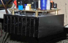
Yes in these profile your heatsink bigger than I taught.
Still be careful the 40V rail voltage a bit close to the max on one pair TIP transistor.
The driver does not need heatsink.
Please replace the input transistors and the BD139 to.
I advise to get read of that cap multiplier stuff and use a CRC capacitor bank.
If you have time, energy etc please test my PC board, that was carefully designed , tested and tested again until I get the best performance as possible.
Also those caps especially the Samwah very bad for audio..
I do have very negative experience with.
I know you just built these amp and just test it now but soon you will realise what I'm talking when you start swap some of those devices.
What type of Sanken darlington you guys has?
I do have some ON semi rugged TO3 case darlington, I have to test them.
You know N Pass A40 also use darlington power transistors..
All do that amp was designed decades a go we can still get information for transistor replacement at Mr. Pass website.
That is a Class A amplifier and different design but sound very good.
Mark Finnish built that amp long time a go, after built a Aleph5, Aleph4, and SOZ.
He wrote there is something in the sound of the A40 what he miss when he listening the Aleps or SOZ.
The reason I wrote done these darlington can sound great if everything properly matched and set up well.
I saw A40 built with TIP142/147 to..
Now I tried to use the TIP darlington in the Eliot Cap multiplier circuit. There the result was disaster, horrible.
So I replaced with ON semi transistors (built up Darlington) it got better but still far from good.
I do had a old JVC receiver with 2SA1095 and complementary and the driver 2SA968 with complementary.
I knew that was matched up in that amplifier so I used those transistors.
The result was excellent!
I didn't tested that set transistor in these amplifier because I have only one pair.
But from that I know the darlington device can be built to get great result.
I did tried and tested some ON semi transistor built up darlington but with a very bad result.
I spoke with a engineer and he told me if I build a darlington from regular BJT I must calculate the transistors Fz, speed, capacitance etc to get good performance.
So I gave up my research. Way back I didn't had Internet so that made my life more difficult.
At my last test even with the mentioned cheap darlington with these drivers ans JFet on the input I got excellent performance.
I'm satisfied with the sound of the amp now again.
That not mean I'm not open to do more test but I got tired over the years. Also now I'm satisfied and happy with the sound.
Only reason I do search for more rugged output device that would make the amp more stable, a piece of mind.
Again I do built some great amps like Symasym, Profet, Aleph30, Aleph X, Hiraga Class A, M Hiraga, some tube amp, P Daniel chip amp so on.
The little amp beat those so much even a so called non Audiophile guy could hear the difference.
An older, experienced gentleman came to my home for some listening seance and testing.
At firs he could not believed that amp drive the speakers the way like that.
The amp was just built on a PC of plywood..
He put his hand on the speaker cable and followed until the speaker from the amp and back..
To him still was unbelievable.
Not one or two guy ask me to build the amp to them and they pay good money for.
So if the amp is beaten by an amplifier from the shelf that mean to me there is a lot of improvement available..
That not mean the amp is unbeatable, just it hold his place even against the big guns to.
Greetings G
.....Yes in these profile your heatsink bigger than I taught.
Still be careful the 40V rail voltage a bit close to the max on one pair TIP transistor.......
The supply sags on playing loud. My scope unfortunately has a problem with the switches so the display is not accurate vertically. So I can't confirm what the real clip level is.Will have to fix this or buy another scope. Will try to fix the dead scopes first. Maybe just spray Doxit-D5 on the switch contacts first!
........The driver does not need heatsink...........
Most likely. But it does get slightly warm. Will remove it and see what happens to the bias drift.
.......Please replace the input transistors and the BD139 to.........
Yes I will search for the BC560C. It has to be here because I bought both pnp and npn at the same time.
......I advise to get read of that cap multiplier stuff and use a CRC capacitor bank..........
The cap multiplier does improve the PSRR especially at the LF end. But I did plan to remove it and make a comparison.
.......If you have time, energy etc please test my PC board, that was carefully designed , tested and tested again until I get the best performance as possible........
Let me see. Time is in short supply right now !
........Also those caps especially the Samwah very bad for audio........
Well the amp still sounds very nice even with it. Maybe better with Nichicon or Panasonic or others. Will check this out.
.......At my last test even with the mentioned cheap darlington with these drivers ans JFet on the input I got excellent performance.........
I will try out the input FET's ( 2SK246/J103) I also have the 2SK170 but not sure about the complement 2SJ74.
............Please replace the input transistors and the BD139 to.........
I will try out the input FET's ( 2SK246/J103) I also have the 2SK170 but not sure about the complement 2SJ74.
It would be good to test the drivers with out heatsink and with heatsink I mean to make some measurement.
I never did it.
I touched any time only it get slightly warm. In case the heatsink help to make the amp more stable please use it and let me know.
Thank you.
Be careful with the 2SK246/J103 those are not the same like the 2SJ74BL/2SK170BL.
If you do not have please stick with BC550C/560C.
The biggest difference between the JFet and BJT warmer sound to the favour of the JFet, there are some other differences but if you don't have.........
Those are hard to get and expensive today and only BL type the direct replacement for the BJT.
Yes I understand your amp sound good even with the Samwah caps to but I know how bad they are for audio. I did tested in the Symasym and after few sound track I trow them away... They are that bad!!!!

Panasonic FC great bad but in the bass area a bit weak.
Nichicon Gold or MUSE (the black) not expensive and great value for the money.
BD140 you need on the heatsink, also it influence the bias set up. I'm amazed the amp works properly with the BD139 to.
I understand hard to swap components because your PC board design (mounted on the heatsink).
That is why I don't like that type of PC board specially until the amp thoroughly not tested done to the last components.
I do had a friend who always designed our PC board that way with software.
I do hate that, when I want to test something always has to be removed from the heatsink..
It take lot of time, most of the time I'd rather left the amp how it was.
But you can mount my PC board the same way like yours to because small compact size..
All that I asked from you please take it as a advise only!!
Only one think motivated I know the amp, I tested thoroughly over 20 years, I used a lot of parts it does sound good with most of them but with the rightly matched components it is incredible good.
OK please enjoy your amp and when you find out new thinks, improvement etc please share it with us.
Thank you
Greetings G
Member
Joined 2009
Paid Member
There are two threads that I am following with interest at the moment - this one, and the one on P3A upgrades. I wonder if anybody has both amps that they could compare them since they are both radically different topologies that such a comparison would be quite interesting !
Yes that comparison would be interesting. However both output devices should be similar types , either LatFET or Bipolar.
G: The BD139 or BD140 will work well in the same place provided the variable resistor is located in the base emitter section. Otherwise I don't see any difference apart from polarity issues. It's only a voltage multiplier.
G: The BD139 or BD140 will work well in the same place provided the variable resistor is located in the base emitter section. Otherwise I don't see any difference apart from polarity issues. It's only a voltage multiplier.
- Home
- Amplifiers
- Solid State
- My first DIY amplifier 20 years a go