If someone wants to build it but does not understand my layout PLEASE ask and I am happy to help you!
Lets go back to the mentioned problem why I got a thermal runaway.
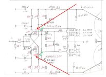
The two 100K resistors was removed ( marked with green) (they does not much in the circuit), that is how the original was drawn.
With that the Miller capacitor (marked with red) become total noneffective.
I forget to correct that in my previous layout and that led to almost burn my Visaton speakers to.
IT is corrected now, should work properly.
Bigun very soon I will test the Sanken Darlingtons you got. I got some from a dismantlement Sony AV receiver.
Lets go back to the mentioned problem why I got a thermal runaway.
The two 100K resistors was removed ( marked with green) (they does not much in the circuit), that is how the original was drawn.
With that the Miller capacitor (marked with red) become total noneffective.
I forget to correct that in my previous layout and that led to almost burn my Visaton speakers to.
IT is corrected now, should work properly.
Bigun very soon I will test the Sanken Darlingtons you got. I got some from a dismantlement Sony AV receiver.
Attachments
Here we go again.
Last week I put together two channels of this amplifier. I used some of my old PCB but corrected the previously overlooked errors.
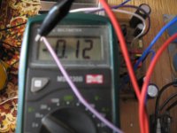
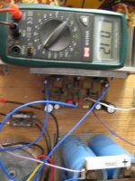
I powered up one channel and set up the bias to 120mA (it is high but for testing) too see if is stable. (around 40V rail voltage)
The amp is on about 3 days continuously and rock solid, no movement or bias wandering like before.
I did not listen yet, I will have to ad some volume control and some RCA connectors.
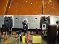
The side now is on it uses a pair BDW83/84D type from ISC.
It used to blow up after I powered up with those transistors. (The amp was oscillating that much)
I always thought because fakes all do it was ordered from Reichelt Germany. (I do not own a scoope).
Again one more time the amp is stable with those power transistors which used to blow up at power up or less than 30 minutes after power up.
The other PCB uses Sanken power Darlingtons, soon I power up that side to. (Gareth ask me long time ago to test those transistors).
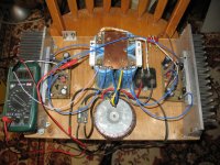
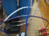
Some picture, I use large can caps even for testing, it is my set up to test different amps.
Last week I put together two channels of this amplifier. I used some of my old PCB but corrected the previously overlooked errors.
I powered up one channel and set up the bias to 120mA (it is high but for testing) too see if is stable. (around 40V rail voltage)
The amp is on about 3 days continuously and rock solid, no movement or bias wandering like before.
I did not listen yet, I will have to ad some volume control and some RCA connectors.
The side now is on it uses a pair BDW83/84D type from ISC.
It used to blow up after I powered up with those transistors. (The amp was oscillating that much)
I always thought because fakes all do it was ordered from Reichelt Germany. (I do not own a scoope).
Again one more time the amp is stable with those power transistors which used to blow up at power up or less than 30 minutes after power up.
The other PCB uses Sanken power Darlingtons, soon I power up that side to. (Gareth ask me long time ago to test those transistors).
Some picture, I use large can caps even for testing, it is my set up to test different amps.
Attachments
Hi gaborbela,
Very good! I'm so happy for you.
You really do need an oscilloscope! An analogue, dual trace, 100 MHz is not expensive these days. A digital scope has toys but they are not as good. Please try and get one, it will make your life much easier and more enjoyable.
When you change output types you can get stability problems (that's why you need a scope). Same for some other circuit changes that may change the bandwidth of some stages. Between that and your layout issues you mentioned, you got it working. We still don't know how stable it is though. You do need to watch the bias current as it runs. Sometimes amplifiers can look fine for a bit, then "take off" once things warm up and the bandwidth and beta shift in some devices. Also watch heat sink temperatures.
So ... what are your plans going further? Probably want to drop the bias current a bit. A distortion analyzer and oscilloscope are so valuable here. If you are very careful, you can use your sound card and something like ARTA to look at distortion. But remember, sound cards often have a 5 volt limit on the input before damage. You need to figure out what your peak voltage is (not the rms value). You would probably want to use a resistive divider on the input. There are some "front end" circuits and projects on here for that purpose. I would maybe start with a -20 dB pad for starters (that's a 10:1 divider). You do want to load it resistively for testing. You can get 8R, 20 or 50 watt loads from China pretty cheaply. Mount those on a heat sink.
Good going, and good luck!
-Chris

My first amplifier was the Maplin 50 watt hi fi amplifier in 1980.
I built it for a disco but it wasnt loud enough so I built the Maplin 225WRMS disco amplifier.
I was pretty clueless about electronics back then so amazing it even worked.
It was the earlier days of Maplin where you picked the components you wanted from the Maplin catalogue, filled in an order form with the stock codes and posted it off with a cheque.
Back came the components with usually a couple of items out of stock.
Hi Nigel,
lol! Yup, the bad old days!
Then there was the ETI amp, many built those over here and I spent years fixing them. I may even see another someday. But, at least people were building things with their hands and enjoying their work.
We did similar things here, but normally called our order in. Electrosonic here was big and they usually had everything. They were expensive though.
Finally.......
I managed to power up the other side, it was not easy.
First I already soldered a pair Sanken darlington (I made a promise to Gareth) I will test those in this amp.
It did not work out. After power up with a 40W light-bulb I got 400mA bias which I could not adjust and the light bulb was on full power.
If not the bulb I would experience the magic smoke escape from the parts.
Interestingly I did not got any offset (DC) voltage on the speakers terminal even with that high bias. There is a reason I mention this.
So I removed the Sankens and the (BD136) TRANSISTORS.
I chose a pair BDW83C/84C in place of the Sankens and a new BD140.
I checked all the solder joints and everything was fine.
I powered up and I ended up -19.5VDC on the speakers terminal. About half the rail voltage (?), I could not find any error. Now I can adjust the Bias but that high voltage on the speakers terminal not OK.
I dismantlement again, I took out all the transistors, including the VAS transistors.
I replaced again the BD140 with Philips. I replaced the BDW-s with TIP-s.
Now It is working, I powered up, I set up the bias to 120mA and will leave it to see the stability or the bias drift if any.
I think tomorrow I will ad a par RCA connectors, a volume control and I will test it the sound.
It should be as good as last time.
When I measure the Sanken or the BDW darlingtons with a DMM it looks like they are OK.
The Sankens were savaged from a Sony home theater receiver which was working OK.
I do not understand, neither the BDW's why acted so weird. I will test it once again later.
Just wanted to be sure I can power up this amp also.
The other side after 3-4 days was rock table I turned down the bias to 50mA. I will do the same with this side also.
Attachments
Hi gaborbela,
Transistors can be faulty and test fine for low voltage gain or diode junctions.
Coming from a hobbyist background, I tended to try and use used parts for my own experiments. I learned the hard way that, although many times it was okay, many times it took days of troubleshooting to come back to a bad part I saved and used. You only use good parts right?
Today, I only use new parts in my experiments. I do not have the time to waste.
I agree with you.
Sometimes Hfe test OK and in the circuit, in real life does not work.
I only try those Sankens because they were removed from a functioning receiver.
Now I know both channel works and it is OK to experiment and do A-B testing.
Of course I change one set of power transistors or VAS ones at the time or other parts and test it.
I hate troubleshooting, it brings back all my failure when I could not find a problem, I could not overcome.
Right now I work on an other amp also which has some stability issue to.
It is a Japanese Kaneda type simple mosfet amp.
One day I may post about. More test need to be done.
At least the bias now it is stable with both type of Darlingtons BDWs and TIPs.
I could not wait longer so I added a pair RCA connector and a cheap Alps pot.
I did listen 2 CDs on her, both channel working properly. Bias set up about 50mV.
The sound quality right now about half maybe 60% of the potential (what I did heard from her previously).
Right now the 40W light bulb still parallel connected with the amplifier.
That kills the music dynamics also steal a lot from the rail voltage.
Having said that the light bulb (helps a lot) it shows me when the dynamics in the music is increasing or the total bias goes higher. It light up stronger.
I will use the amp for a couple days like that.
It is easier while listen music to take a peak time to time on the light bulb how much it glows than check the DMM.
I can do it in the dark to.
With this set up from the 25VAC 250VA toroidal transformer I get about 26VDC when the music is loud, about 29-30VDC when the music stops.
At the moment I use a cheap 4.7uF WIMA DC blocking capacitors on the input and Panasonic FC capacitors which is not the best with a warmer sounding amplifier.
Right now I am very happy, it look very promising and stable.
The sound of the amp will improve I know, I do not worry about that.
I know the sound of the amp!
Your coupling capacitors will not change the sound of the amp. I know the 4u7 Wima caps. They are fine. The light bulb is killing the dynamics.
There are other components that might improve sound quality, but that is something I would need to check on my bench with my equipment.
Enjoy!
There are other components that might improve sound quality, but that is something I would need to check on my bench with my equipment.
Enjoy!
Member
Joined 2009
Paid Member
Member
Joined 2009
Paid Member
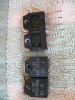
I found a thread, where it is claimed that those particular Sanken parts are very hard to bias. This is what I found:
“Yes, they're sonically very good, especially for darlingtons. They're very fast and have reasonable SOA. Darlingtons in a Class-AB/B Emitter Follower have a relatively small Vbe-biasing sweet spot, and Sony apparently uses a carefully-controlled Sziklai Vbe multiplier with a hi-beta (>1000) master to achieve this.” https://www.diyaudio.com/community/threads/sony-5-1-output-transistors-repair.36422/
So maybe not any fault of your circuit, just not suitable.
I just went to my basement and found these objects, I feel very attracted to this amplifier. I am so busy these days but if I can find some time I would like to see if my Sanken devices could possibly work….🙂
Attachments
Last edited:
I will test it one more time later. Mr. N Pass has that Class A-B AMPLIFIER schematics with TIP 142/147 Darlingtons. Some DIY-ers built it with the mentioned Sankens and they work properly. That has a similar VBE as this amp if I remember well. I also want to test it for myself I have at least 10 pair or so at hand and I still have a cheap Sony receiver one channel dead with the same Sankens.
Yes..Just for info, the Nelson Pass Darlington amp is the AB100
It runs smooth both channel without any issues.
The bias is stable (first time ever), rock solid!
Soon I will remove the 40W light bulb which now is connected in parallel with the whole amp.
I will do some serious listening and will test different type of Darlington transistors what I collected over the years.
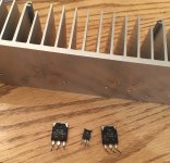
Also for the VAS (driver stage) I have some original Toshiba, Hitachi and Sanyo transistors.
Right now I use On Semi MJE243/253 there.
I know that not means automatically it will improve the sound but why not test it if I already have those?
This ( old PCB) is only a test model, I have a new improved layout corrected the previous errors.
With 2 or 3 pairs power transistors and I will go a bit higher with the supply voltage at the final setup.
The bias is stable (first time ever), rock solid!
Soon I will remove the 40W light bulb which now is connected in parallel with the whole amp.
I will do some serious listening and will test different type of Darlington transistors what I collected over the years.
Also for the VAS (driver stage) I have some original Toshiba, Hitachi and Sanyo transistors.
Right now I use On Semi MJE243/253 there.
I know that not means automatically it will improve the sound but why not test it if I already have those?
This ( old PCB) is only a test model, I have a new improved layout corrected the previous errors.
With 2 or 3 pairs power transistors and I will go a bit higher with the supply voltage at the final setup.
- Home
- Amplifiers
- Solid State
- My first DIY amplifier 20 years a go