lineup said:I have not seen any diode into base of any vas transistor of aksa
Sorry for not being clear about that. I was referring to the schematic of the 1999 Halcro patent.
andy_c said:
This trick seems to be specific to his particular design though. The CE transistor of his VAS has a diode in series with its base. So the idea was apparently to match the Vcb of the two transistors in the mirror, given that odd VAS configuration (VAS diode seeing base current of VAS CE stage, mirror diode seeing base current of mirror stage).
Hi Andy.
Thanks for the clarification
")
Cheers,
Glen
jam said:PMA,
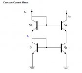
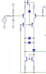
Is that some form of cascoded Widlar mirror?
Jam
It is Camenzind. Yes, cascoded.
http://www.designinganalogchips.com/_count/countdown.pl?designinganalogchips.pdf
Enjoy.
G.Kleinschmidt said:
I suggest your method of simulation is suspect. This issue is with the linearity of the circuit at high frequency when the LTP is NOT operating at a "low AC current swing".
You simply cannot expect a high degree of HF linearity (working against the BJT junction capacitances) from a diode forward biased with a few tens of uA..
Cheers,
Glen
I can't argue with the rationale but for small signal devices such as MPSA18 etc which are often used in mirrors, the cob amounts to about 2pf at 0.4V. At a lowly 0.01mA the dynamic resistance of a 1N914 is still no more than a few hundred ohms so it's difficult to easily see an issue here. Even at 20KHz the cob XC is about 10000 times smaller than the diode resistance.
That said I think your suggested 3 transistor + bias resistor is an excellent solution all round.
Cheers
VHF man said:
I can't argue with the rationale but for small signal devices such as MPSA18 etc which are often used in mirrors, the cob amounts to about 2pf at 0.4V. At a lowly 0.01mA the dynamic resistance of a 1N914 is still no more than a few hundred ohms so it's difficult to easily see an issue here. Even at 20KHz the cob XC is about 10000 times smaller than the diode resistance.
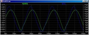
But you haven’t detailed the issue here. The problem is the susceptibility of the diode to reverse bias due to its low quiescent current. See the attached graph. This is from a simulation of a wide bandwidth opamp (at 20kHz) with the diode modification to the current mirror.
The LTP tail current is 5mA, the blue trace is the diode current and the green trace is the resultant collector voltage of the “diode” transistor of the current mirror.
Note that the average diode current is approximately 12uA. This is because high beta transistors are used. You can see that the negative peaks of diode current drop to 0uA (the diode is reversed biased during this period).
With some experimenting I’ve found that the problem can be alleviated up to and beyond 20kHz by deliberately selecting transistors with low beta (for a higher diode bias current) combined with low Cob, but current mirrors generally perform better with low Cob devices that have high rather than low beta, making the net worth of the added diode about nill.
Cheers,
Glen
Attachments
lineup said:i see 4 mosfets
i am 99% sure it is a very good mirror
But there are many different mosfet.
Are you using IRF610 = TO-220 ?
If they are TO-92 mosfet.
Which are the suitable for your mirror, PMA?
As I did not receive a reply.
Let us see a practical implemention of your 4 MOSFET mirror, PMA.
I think you can do it, man!
Abstract mathematical theoretical perfect mirrors for use inside chips is fine.
But most of us do not make their own current mirror IC-s.
If you recommend an arrangement of 4 MOSFETs
is this in any way practical useful for our own amplfiers?
Regards.
- Home
- Amplifiers
- Solid State
- Current Mirror Discussion