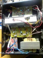
i have an old mosfet amplifier that (you can see) is a DIY job. it says 600W output but im not sure about that. it has overload protection in the form of relays on the output, and one channel kicks out even at low output levels. and the amp sounds horrible.
so i was wandering what is the best thing i can do with this amp?? should i try and fix it or build a new amp from scratch?? i will obviously use the transformer, and maybe the output transisters???
i know i haven't given many details about the amp, but if there some measurements i should take please let me know.
i want to use this amp in a PA/ small disco system, and add a limiter to it so i (or anyone else using it) cant blow the amp or speakers. this will be my first amp project, so i would like to have things as simple as possible
so the transformer is pretty big (and heavy). its 38-0-38 which pushes out about +- 50v dc. i have no clue how much current i can draw from it but this thing looks pretty industrial!!
transisters are MJ15024
got some pics here, sorry about the quality but i had to compress them to attach:
transisters are MJ15024
got some pics here, sorry about the quality but i had to compress them to attach:
Attachments
i have an old mosfet amplifier that (you can see) is a DIY job.
It seem you have a BJT amp here , not a mosfet , as MJ 15024
is npn 250w. With the hardware you have here, you have many
choices.
First , with 38-0-38VAC , that gives about 52-0-52 VDC
allowing for a 120w amp. looking closely at it shows its age,
so the caps should be replaced.
The present amp has design considerations (VAS on main HS,etc
)but there are many amps here that would work with
this "shell". the "power amp under development' (NMOS 200)
or in a couple days , my amp "frugal amp"
are modern amp designs which would seemlessly just
"bolt on" to what you have already.(they use the same L channel
for outputs)You could repair it but that is up to you.
Dont throw it out because I just had to spend 250$+ to get what
you have. (Case , trafo, Heatsink)
OS
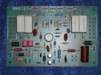
I can confirm it's a PA300 amplifier board. Look at the diagrams here - the layout is identical.
http://www.reber.si/ojacevalniki/PA300/PA300.htm
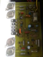
Is the closeup pic of the PCB the faulty channel? I see heavy scorching around several resistors.
As you now have the schematic and PCB layout, you could repair it... but i would be wondering why it failed and why those resistors overheated in the first place... it could be a design flaw.
Maybe someone here knows the PA300 circuit better?
edit: from the look of it the fried resistors are R13, R15, R18 and R19. That would suggest the VI limiting circuit has been activating frequently, ie the amp has been severely abused. I would test the output and driver transistors, replace the scorched resistors, replace T1, T3, T4 and T5. You might also want to check the diodes around that part of the circuit.
http://www.reber.si/ojacevalniki/PA300/PA300.htm
Is the closeup pic of the PCB the faulty channel? I see heavy scorching around several resistors.
As you now have the schematic and PCB layout, you could repair it... but i would be wondering why it failed and why those resistors overheated in the first place... it could be a design flaw.
Maybe someone here knows the PA300 circuit better?
edit: from the look of it the fried resistors are R13, R15, R18 and R19. That would suggest the VI limiting circuit has been activating frequently, ie the amp has been severely abused. I would test the output and driver transistors, replace the scorched resistors, replace T1, T3, T4 and T5. You might also want to check the diodes around that part of the circuit.
thank you thank you thank you!!!
i think with all this info i am going to repair this amp.
as for the output transistors, they are not the same as the one's in the schematic. (i called it a mosfet amp 'cos its written on the case - sorry) in SA we have trouble getting components so i guess the MJ15024's were the closest that could be found at the time.
both channels are working on this amp - but power output is not great, and one of the relays cut out (although not with music, just when it was used for a band with guitar and vocals)
i only have a multimeter to test with, so are there any tests i can do to check output transisters etc?? and is there a way i can test the protection circuits without using a speaker?? ( cant really play music super loud for a long time, parents would kill me )
)
i think with all this info i am going to repair this amp.
as for the output transistors, they are not the same as the one's in the schematic. (i called it a mosfet amp 'cos its written on the case - sorry) in SA we have trouble getting components so i guess the MJ15024's were the closest that could be found at the time.
both channels are working on this amp - but power output is not great, and one of the relays cut out (although not with music, just when it was used for a band with guitar and vocals)
i only have a multimeter to test with, so are there any tests i can do to check output transisters etc?? and is there a way i can test the protection circuits without using a speaker?? ( cant really play music super loud for a long time, parents would kill me
)Hi Dan2!
It looks like the Power Transfomer is too small, egg low
VA.
Calculate for one Ch. min. 350-400VA x 2 700-800VA.
On Picture 1 P. Tr. look like Max. 450VA.
On att. pic is My aproach for this Amp without protection crcuit!
Only sample!
Regards zeoN_Rider
It looks like the Power Transfomer is too small, egg low
VA.
Calculate for one Ch. min. 350-400VA x 2 700-800VA.
On Picture 1 P. Tr. look like Max. 450VA.
On att. pic is My aproach for this Amp without protection crcuit!
Only sample!
Regards zeoN_Rider
Attachments
MJ15024/5 are actually a superior substitute for the listed MJ15003/4 transistors, so that is OK
Maybe it says MOSFET on the front because some person reused an old amplifier for parts. That would certainly be reasonable.
I must say at a second glance, the mains wiring inside it looks dreadful. Please be careful.
I would second Zeonrider's opinion that the transformer is not up to the job of running two 300W channels. This is probably why the sound quality isn't good, and why the protection is activating as the power supply sags, and the protection circuit mistakes it for DC on the output.
One channel has definitely been abused as mentioned above - the black scorching around several resistors looks to me like the VI limiter circuit has turned on hard quite frequently.
yes, when the protection circuit kicks in it turns on and off frequently untill you tuen the amp off.
as for replacing the transformer - i am not trying to get 300W per channel out of this thing. i have a pair of Zomax P-1565's which run pretty well on about 50w, and i want to get a pair of 12" speakers to go with it. i also want to build an active crossover (one amp for mids and one for bass) and put in a limiter circuit. i have looked at Rod Elliott's website and he has a few circuits for that.
do i need a pre-amp for this amp??? i want to connect it straight up to a computer sound card.
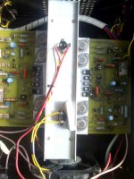
ok, so i have taken the amp out to take a closer look.
i have spotted a few differences between the schematic and my amp so please go through this with me: (i have two of these amps and the differences are the same for both of them)
C5 is electrolytic - i dont know what type of cap it should be.
the wire link from input (-) to output (-) is replaced with 10 ohm resistor. is this to prevent ground loops???
R39 (temperature sensor) is not on the board, and the wire link from T13 to the relay is missing. so the components for the thermal protection are on board, but not being used
( i see now the protection circuit was only used for power-on delay, am i right? but then how did the relay switch on and off after it was powered up?)
D14 (LED) was never connected (also part of thermal protection)
R18, R17, R12, R15, R13, R19 were fried and most of them replaced. are these also part of the protection circuit??
can someone also explain to me what should be connected to "AC clip"?? it was an LED but on the schematic (D12) it looks like an input
PS as for the transformer, i really do not want to replace it and actually can't affort to at the moment. i am not looking to get 300W per channel out of this thing - i just want to have it reliable.
......and one more thing. if i am going to replace the PSU caps, do i need to replace ALL the caps on the amp?? or just the electrolytics?? will this help with the lack of bass??
Attachments

- Status
- This old topic is closed. If you want to reopen this topic, contact a moderator using the "Report Post" button.
- Home
- Amplifiers
- Solid State
- Repair or Replace??