lineup,
Yes, a good power supply is indicated. Shunt, series, or both. Given that the circuit itself is not complicated or expensive, you can put the money you save into the power supply. Might be a good time to throw Walt Jung's regulator into the fray.
GuidoR,
The IRF50 will do a splendid job. I used the '610 because I've got a bunch of them and I could lay hands on them easily. For that matter, I've got some '510s, but I'm not sure where they are. Feel free to experiment with the cascode device.
Yes, the SSTART should do a pretty good job with the F4. Should you want a bit more voltage swing, the SSTART can be goosed to a higher rail voltage. Keep the cascode device at about the same level by recalculating the voltage divider. Increase the load resistor value to compensate. Poof! You're done.
(What's a Shiny? I'm sure there's a thread somewhere that would answer my question, but I've been so busy working the stock market that I haven't kept up with stuff here...including this thread. Sorry 'bout that.)
tschrama,
I'm not following what you mean about wrong thread. Maybe just lack of sleep.
Fred? I'm sure you know where to find him if you feel you need a dose of bad behavior.
massimo,
Approach this sort of circuit with care. One thing to watch out for is that the MOSFET's Gate will bounce to its operating voltage instantly at turn-on. The tube, however, will not conduct until the filament heats up, some ten seconds later. This could easily exceed the Gate-Source KAFLOOIE voltage. It's not an intractable problem, but keep your eyes open.
I confess that I am not a fan of running 6DJ8/6922s at reduced plate voltages (by which I mean 90-100V). Yes, folks do it, but you're giving up one of the prime benefits of using tubes.
If I were to do it, I'd use the 6DJ8, not to replace the JFETs, but to replace the MOSFET. Then I'd set the rail to something like 100V, maybe 125V. Reduce the bias current in the JFETs a bit or you'll overdo the tube. (Can't remember the current rating for the 6DJ8 offhand, but I'm pretty sure that it would be unhappy with 20mA and any decent rail voltage...)
Or you could just forgo the cascode device and run the tube by itself...maybe parallel a few to get the current up and the Zout down...oh, wait, someone's already done that...
The 2SK246 would be a great option. The Source resistors will need to be lower., but otherwise it will do a fine job.
tschrama (again),
As long as you keep an eye on your Pd per JFET you can fiddle to your heart's delight. The J310 can pass a surprising amount of current for such a dinky device, but it can't take much heat.
Did you try it with high signal levels?
Grey
Many thanks Grey
The 6DJ8 won't survive at 20 mA.... for sure. 90-100V at the anode its the tipycal B+ for this tube. Some nice examples at 40 V exist when low noise is requested (i.e. MC pre-premp)
That's was just and idea....
I'll order some J310s asap, than maybe try the 2sk246 halving the source resistors value.
Hi Grey,
Yeh, here is what I did:
I adjusted the Cascode voltage while monitoring the output (12Vpp). In my case, there is a certain point where the 2nd harmonic vanishes.. I could clearly see that on the FFT of my digital scope. I measured the Drain voltage at the JFETS, it was around 4.14Volts. @nd harmonic completely vanishes, 3rd harminic rises a little bit, total THD was lowered by about 10dB.
If you over do it, and the cascode voltage becomes to low, then suddenly all kind of higher harminics appear.
cascode voltage:
9Volt: mainly 2nd, little 3rd harmonic, THD:-40dB
4Volt: only 3rd harmonic: THD:-52dB
3.5Volt: a whole train of harmonics.
There are more threads about JFETs and 2nd harmonic canceling (JFET BOZ, ZV9 , JFET pacific riaa)..
Another thing: have you read this, what do you think about it:
fetzervalve
cheers,
Thijs
massimo said:
Some nice examples at 40 V exist when low noise is requested (i.e. MC pre-premp)
I've seen a few (e.g. Sunfire preamp), but regard them more as oddities than a successful strategy. Audio Research, among others, tend to use the JFETs as gain devices and tubes as cascodes. To the extent that you want low noise, you're better off with the first stage being a JFET than a tube. Much better. Tubes do a lot of things very well indeed, but noise isn't one of them.
tschrama said:
I measured the Drain voltage at the JFETS, it was around 4.14Volts. @nd harmonic completely vanishes, 3rd harminic rises a little bit, total THD was lowered by about 10dB.
If you over do it, and the cascode voltage becomes to low, then suddenly all kind of higher harminics appear.
Another thing: have you read this, what do you think about it:
fetzervalve
The trick to reducing distortion this way is to match the curves of the gain device against those of the cascode device. If you're using a JFET--which has an overall gain curve resembling a pentode--you're generally going to find that a lower Drain voltage puts you down into the triode portion of the curve. All is well...until you hit the thing hard, at which point the signal leaves the triode portion of the curve and distortion not only increases but changes character rapidly. Or you can look at it in terms of available voltage swing between the gain device and cascode. That's why I asked you about high signal levels. If you're driving a sensitive enough amplifier, you'll be okay, but if you intend to use the SSTART to drive a follower amp (as per GuidoR's post, above) then the circuit becomes unsatisfactory. What's the point of having 35V of voltage swing if you can't use all of it cleanly?
The upshot being that if you have an amplifier that can be driven to maximum output with a smallish signal, then you're home free with a lower cascode voltage. But to make the circuit applicable in a wider assortment of systems, I went for a wider voltage swing.
Musicians have had a love/hate relationship with solid state from the beginning. The reliability is seductive, but the sound often left them cold. Being a bass player myself, I can live with the sound of solid state better than guitar players. Everything has been tried: All solid state, tube front end/solid state output hybrids, solid state front end/tube output hybrids, and all sorts of clever attempts to make solid state "sound like tubes." They've gotten better over time. (I ran across something not long ago that claimed that the Kustom solid state amps from the '60s were hot collector's items. For the life of me, I can't understand why--they sounded like crap.)
That said, the circuit described in that link might be worth investigating. In a quick read, I got the impression that they were trying to reduce distortion rather than purposefully add distortion, so it might be fun to try.
Grey
I wonder why so few people asked for this project.
Is it so simple that even a newbie can build it without errors?
But, being me less than a newbie, I need some other advices.
Speaking of J310's Idss: mine are all in the range of 40mA. You suggest in the article to lower the voltage to 8V. But how's the math? (I know, this question is briefly "how a JFET works" but I am a newbie ) .
) . ") devilr: Guido, don't only ask, study electronics instead...)
devilr: Guido, don't only ask, study electronics instead...)
And then: how to compute the value of the load resistor?devilr: and english, also)
Many thanks
Guido
Is it so simple that even a newbie can build it without errors?
But, being me less than a newbie, I need some other advices.
Speaking of J310's Idss: mine are all in the range of 40mA. You suggest in the article to lower the voltage to 8V. But how's the math? (I know, this question is briefly "how a JFET works" but I am a newbie
) . devilr: Guido, don't only ask, study electronics instead...)And then: how to compute the value of the load resistor?
devilr: and english, also)Many thanks
Guido
First you have added your J310, any number
using 100 Ohm at each gate and 47 Ohm for each emitter (instead of 51.1 Ohm)
and added the IRF610 biased by 10 kOhm + 22 kOhm (R5, R4)
Then you can put one 10 Ohm resistor in place of R8 (270R).
The goal is to get a voltage drop across R8 of ~17.5 Volt. (Between 15-20 Volt is alright)
Now measure the voltage across this 10 Ohm resistor.
We call this voltage MV = Measured voltage.
This is how to calculate the value for R8:
R8 = 17.5/MV * 10 Ohm
Find a resistor close to this value.
Use a 5 Watt power resistor.
Attachments
The above method assumes a power supply ~50 VDC. = Default GRollins supply.
For like 40 VDC supply, we may want ~15V across R8, and you could use formula:
R8 = 15/MV * 10 Ohm
For like 60 VDC supply, we may want ~20V across R8, and you could use formula:
R8 = 20/MV * 10 Ohm
For like 40 VDC supply, we may want ~15V across R8, and you could use formula:
R8 = 15/MV * 10 Ohm
For like 60 VDC supply, we may want ~20V across R8, and you could use formula:
R8 = 20/MV * 10 Ohm
By all means, feel free to experiment with the circuit, but bear in mind that the J310 is only rated for 350mW. The SSTART runs them around 250mW as it is. A TO-92 case device can do this fairly comfortably, but don't get too excited.
On the other hand, the J310 is damned cheap by today's standards, so feel free to burn a couple of them if that's your cup of tea. Hurts my Scottish soul to ruin a perfectly good part, but others may want to attempt to recreate some of the more spectacular SSTAR WARS special effects using J310s as squibs.
The actual parts values and bias are a matter of balancing a number of (sometimes conflicting) requirements. You don't want the thing to clip with a strongish signal, so you'll need some voltage drop across the Source resistors. The more bias you can run, the better. Those two tend to lead you to the value of the Source resistor. Against that, you have the heat dissipation and the gain, which is in part determined by the value of the Source resistor and (to a lesser extent) the bias. If you're willing and able to make do with less gain (and many people are, particularly if they're using only CDs for source material), it opens things up a bit. I was shooting for the ART's stock 20dB of gain, just for fun, but you're under no obligation to hit that mark.
Grey
If they are only rated 350 mWatt (Fairchild SOT-23)
then I would maybe run them at like 200 mW, max.
The Fairchild TO-92 are rated 625 mW, and 60% would give like 360 mWatt, max.
For 12 Volt across them, this would give an absolute max. for me, of 25-30 mA.
As you say Grey, there are several factors to decide how much current to run.
Maybe the most important is IDSS of your J310.
Here is the datasheet PDF for Fairchild J310 and J309.
http://www.fairchildsemi.com/ds/J3/J310.pdf
Attachments


Well, there is something wrong with that 625 mW rating for J310 in Farichild datasheet.
Onsemi & Philips have these figures: 350mW & 400mW.
So Grey is right, run them no harder than 150-200mW.
Max 12-16 mA with like 12 Volt across Drain-Source.
Gives:
12mA x 12V = 144mW
16mA x 12V = 192mW
See attachment.
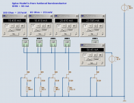
If using the default 50 VDC supply and JFETs so are working at 12V drain-source,
then this simulation renders I should use >= 100 Ohm source resistors
for max 200 mWatt operation.
This is for the Philips IDSS= 50 mA spice models.
So, the advice to use 51.1 Ohm or more is correct. I guess for most J310.
Each one that will build SSTART may do his own measurments.
It is not very difficult math
--
Actually I could use 82 ohm resistor, because there is a voltage drop across this 82 Ohm resistor of like 1.5V.
So the JFET has 12-1.5= 10.5V drain-source.
18.4mA x 10.5V = 193.2 mWatt
Attachments
I wonder if the confusion with power dissipation numbers is that Fairchild have not specified Ta=25degC or Tc=25degC.
These two standards do give different dissipation.
We normally expect to see the 625mW with Ta=25degC, but I suspect that Fairchild have omitted to tell us that the 625mW applies when Tc=25degC.
The dissipation for Ta=25degC will be 350mW and then all the numbers quoted on the datasheet are correct.
If this is the case then Fairchild need to adopt the standard method for max dissipation, they must quote Ta or Tc as appropriate.
Ipanema said:Hi Grey,
Is STAART strong enough to drive a 32ohms heaphone?
Thanks.
Yes, and most probably even 16 Ohms.
32 Ohms or higher is an EASIER, Lighter load..
High quality Sennheiser are so easy to drive
because they are even almost 10 times higher impedance = 300 Ohms
- Status
- This old topic is closed. If you want to reopen this topic, contact a moderator using the "Report Post" button.
- Home
- Amplifiers
- Solid State
- SSTART Preamplifier