Hello,
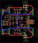
It was raining outside today and nothing good was on the TV.. So I decided to fire up eagle and try to make a very small JLH. I'd appreciate some comments and thoughts on making it even smaller.
Mounted off-board: The fuses, output transistors (& resistors), muting relay and the filtering caps.
Thanks !
Attachments
Hi Yoshy
Here, the rain it is a rare phenomenon already. We have to see rain at least 1 month. Weather is cloudy, almost every day, the temp varies between 12 and 20 deg C and year by year we become Africa.
Anyway, there is no way to reduce your pcb size, its OK. The distance between the smoothing caps it is big. Try to shorten it.
Fill the "T" points on the tracks, with small copper triangles. Avoid the 90 deg corners. They cause parasitic capacitances. Make the supply and 0V tracks thicker.
Regs from north Greece
Fotios
Re: pcb
Yes, all the components on the PCB are rated at least 30v (C1 and C2). I'd have to redraw the PCB and make the traces bigger but higher power is achievable I think.
While I'm sure it has some disadvantages, I wouldn't mind a few months without rain... or snow !
Thanks for the input; about the 0v: would it be better if I used a ground plane instead ? Something like this...
Thanks !
p robertson said:Hi yoshy, is it the 10w class A circuit?
Yes, all the components on the PCB are rated at least 30v (C1 and C2). I'd have to redraw the PCB and make the traces bigger but higher power is achievable I think.
fotios said:Hi Yoshy
Here, the rain it is a rare phenomenon already. We have to see rain at least 1 month. Weather is cloudy, almost every day, the temp varies between 12 and 20 deg C and year by year we become Africa.
Anyway, there is no way to reduce your pcb size, its OK. The distance between the smoothing caps it is big. Try to shorten it.
Fill the "T" points on the tracks, with small copper triangles. Avoid the 90 deg corners. They cause parasitic capacitances. Make the supply and 0V tracks thicker.
Regs from north Greece
Fotios
While I'm sure it has some disadvantages, I wouldn't mind a few months without rain... or snow !
Thanks for the input; about the 0v: would it be better if I used a ground plane instead ? Something like this...
Thanks !
Attachments
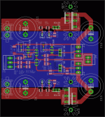
Pingrs said:A small, single sided , non-SMT version of the JLH I made some time ago.
Brian.
That's very nice !
I want to do a SMD version since I have a bunch of 0.1% metal film in 1210 package. I'll will take a look at your layout and see if there's something I can change.
Did you build yours ? And if so are you satisfied with the sound ?
Thanks,
Phil
Pingrs said:A small, single sided , non-SMT version of the JLH I made some time ago.
Brian.
Sure would be nice to see the "black & white" etching image seperate from the silkscreen image of the components. I'd like to give it a go. Can you share a little more? I have most of the parts to give this a try.
I have also PM'"d you but no response.

"Sure would be nice to see the "black & white" etching image"
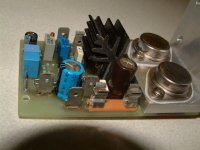
Sorry for the delay; took a break to Scotland.
I built and bench tested this layout over a year ago without any problems but other designs diverted my interest.
Image attached.
Best of luck.
Brian.
Sorry for the delay; took a break to Scotland.
I built and bench tested this layout over a year ago without any problems but other designs diverted my interest.
Image attached.
Best of luck.
Brian.
Attachments
Pingrs said:I built and bench tested this layout over a year ago without any problems but other designs diverted my interest.
Image attached.
Best of luck.
Brian.
Fantastic! Perhaps I play some x-mas music
 on a set of these if I put my nose to the grind stone. Very compact layout and if Yoshy uses SMT devices, it could even be smaller! Thank you.
- Status
- This old topic is closed. If you want to reopen this topic, contact a moderator using the "Report Post" button.
- Home
- Amplifiers
- Solid State
- Comment on PCB and how to make it smaller