I HAVE FOUND THAT A FAST AMP PERFORMS BETTER THAN A SLOW AMP.
THIS LITTLE 30 WATT CLASS A THAT I AM DESIGNING FOR SOMEONE HAS A SLEW RATE OF 580V/uS AND THERE IS NO RINGING OR OVERSHOOT, JUST A NICE SMOOTH-OVER.
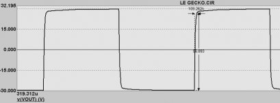
THE FREQUENCY SELECTED WAS 250kHZ. THE AMPLIFIER BAND WIDTH IS CURRENTLY LIMITED 0.1 HZ TO 7.4 MHZ.(-1dB)
SOUND IS CRISP AND VERY CLEAR WITH INCREDIBLE DETAIL. THD AT FULL POWER AND 100Khz IS BELOW THE PROVERBIAL 0.0008%. THE THD AT 1 MHZ 0.003%. AND AT 10 HZ 0.0002%. aT 1 KHZ IT IS 0.000012%
TWO TONES 19KHZ AND 20 KHZ GIVES INTERMODULATION PEAKING AT -134 AND -138 DBC, JUST BELOW THE NOISE.
I AM USING FOUR PAIRS OF 2SK1058 AND 2SJ162
I WAS TASKED TO MAKE THE ULTIMATE AMPLIFIER, IT Makes my toenails curl when listening to Diana Kral.
ISTHERE MORE ISSUES THAT I SHOULD CONSIDER. BESIDES GROUP DELAY, WHICH IS JUST ABOUT 0.138 DEGREES OVER THE 0 - 200 KHZ RANGE.
COMMENT WELCOME.
THIS LITTLE 30 WATT CLASS A THAT I AM DESIGNING FOR SOMEONE HAS A SLEW RATE OF 580V/uS AND THERE IS NO RINGING OR OVERSHOOT, JUST A NICE SMOOTH-OVER.
THE FREQUENCY SELECTED WAS 250kHZ. THE AMPLIFIER BAND WIDTH IS CURRENTLY LIMITED 0.1 HZ TO 7.4 MHZ.(-1dB)
SOUND IS CRISP AND VERY CLEAR WITH INCREDIBLE DETAIL. THD AT FULL POWER AND 100Khz IS BELOW THE PROVERBIAL 0.0008%. THE THD AT 1 MHZ 0.003%. AND AT 10 HZ 0.0002%. aT 1 KHZ IT IS 0.000012%
TWO TONES 19KHZ AND 20 KHZ GIVES INTERMODULATION PEAKING AT -134 AND -138 DBC, JUST BELOW THE NOISE.
I AM USING FOUR PAIRS OF 2SK1058 AND 2SJ162
I WAS TASKED TO MAKE THE ULTIMATE AMPLIFIER, IT Makes my toenails curl when listening to Diana Kral.
ISTHERE MORE ISSUES THAT I SHOULD CONSIDER. BESIDES GROUP DELAY, WHICH IS JUST ABOUT 0.138 DEGREES OVER THE 0 - 200 KHZ RANGE.
COMMENT WELCOME.
Attachments
Nico,
With those measurements, and particularly with that sound as you describe, I doubt more needs to be done.
Are those measurements made empirically, or using PSpice?
Except perhaps that you should have it made in China and sold worldwide for $1k!!
Hugh
PS: Your graph measurements indicate 520V/uS, in fact, and you should specify a particular frequency if you quote group delay in degrees......")
With those measurements, and particularly with that sound as you describe, I doubt more needs to be done.
Are those measurements made empirically, or using PSpice?
Except perhaps that you should have it made in China and sold worldwide for $1k!!
Hugh
PS: Your graph measurements indicate 520V/uS, in fact, and you should specify a particular frequency if you quote group delay in degrees......
Nico Ras said:IT Makes my toenails curl when listening to Diana Kral.

Excellent stuff Nico.

Good job... It sound quite out of this world performances, even too good, especially with mosfets. You must rely on a heavy negative feedback to get that out of them, I guess. Linearity is not their best usually. I am curious about a schematic. I didn't think it was possible to get such numbers. Seeing is believing...
Regards
Regards
Hi
Of course a fast amp is better than a slow amp, but the ability to drive a reactive load with stability is quite important. Mosfets are plenty fast enough, if you use them correctly. Do you use local feedback or error correction for the outputs? Vertical or lateral fets? I would guess verticals..... A schematic would be interesting, but I bet your layout has a lot to do with the performance at such high frequencies. I would be more interested in the layout. The class A operation would contribute a lot to the performance because there is no switching off of the transistors. Approximately what price do you pay (in inefficiency) for the class A operation?
just curious
Of course a fast amp is better than a slow amp, but the ability to drive a reactive load with stability is quite important. Mosfets are plenty fast enough, if you use them correctly. Do you use local feedback or error correction for the outputs? Vertical or lateral fets? I would guess verticals..... A schematic would be interesting, but I bet your layout has a lot to do with the performance at such high frequencies. I would be more interested in the layout.
The class A operation would contribute a lot to the performance because there is no switching off of the transistors. Approximately what price do you pay (in inefficiency) for the class A operation? just curious
HAS A SLEW RATE OF 580V/uS
AND THERE IS NO RINGING OR OVERSHOOT
How did you do this?
You have full information about your other amplifiers here:
http://www.digisec.co.za/ras/
But if that amplifier is that good, I would consider selling Diy KITS.
If I were you
Regards, Lineup
Yes, I am quite curious, at 1MHz it would be better than a diamond buffer actually, which has no amplification by the way. I just can't even imagine such performances, and even less a way to measure them accurately. Let us know about the design more precisely. Even with a full current mirror topology and diamond buffer output I couldn't obtain that, would it be with feedback. PLEASE... some schematic!!!
Regards
Regards
lineup said:
How did you do this?
You have full information about your other amplifiers here:
http://www.digisec.co.za/ras/
But if that amplifier is that good, I would consider selling Diy KITS.
If I were you
Regards, Lineup
Hello - Prove it and we will make a lot of money - per@navi-star.com
Nico is very good in Marketing... our curiosity was ligthed
He turned all of us "on"
This is good, some emotions in our lives.... the amplifier cannot be so good as he is saying...but we are interested.
To the ones believe specification sounds, this one may be the "voice of God"
Good Nico!
regards,
Carlos
He turned all of us "on"
This is good, some emotions in our lives.... the amplifier cannot be so good as he is saying...but we are interested.
To the ones believe specification sounds, this one may be the "voice of God"
Good Nico!
regards,
Carlos
lineup said:...If I may guess it is one no-global-feedback design
I can not imagine such a fast amplifier can work with FB
...and how can a no-global-feedback design do THD of 0.000012% ...
AKSA said:Nico,
With those measurements, and particularly with that sound as you describe, I doubt more needs to be done.
Are those measurements made empirically, or using PSpice?
Except perhaps that you should have it made in China and sold worldwide for $1k!!
Hugh
PS: Your graph measurements indicate 520V/uS, in fact, and you should specify a particular frequency if you quote group delay in degrees......
Hi Hugh and other replying,
We are assembling revision 13 PCBs which took us roughly 14 months to develop to this point and is what will be delivered.
Hugh the company we are making it for has its own large automated production line and it would be earmarked for the USA market. (Guess the current economic climate is not great for a new product launch).
To answer your question phase delay is measured across the band by sweeping the frequency 2 Hz to 200kHz (one decade above and below the audio spectrum) and measuring using a network analyzer capable of 10 pico second resolution. All these specs where design requirements, not achievements let me assure you.
With the kind of feedback here I wish I could share it on line, maybe one day we could. Thank you all.
Nico
darkfenriz said:Nico
You are either a genius or a clown.
Hi Darkenfritz,
It was a contract design that utilised several engineers over a period of 14 months this was not DIY.
Steve Dunlap said:If those specs are from a real unit no wonder you are SHOUTING about it. What distortion analyzer were you using? Mine doesn't go that high in frequency or that low in distortion measurement.
Our standard test equipment are Hewlett Packard Anritzu and Rohde & Schwartz, but you are absolutely correct, some test equipment was part of the development.
Thank you Nico,
I wish you every success in this endeavour; the measurements are sensational, I hope you can achieve the contract requirements, this has the potential to sound absolutely supernatural.
I have studied most of your DIY designs on the website, and can see that you have built and tested many amps over the years. Significantly, you do not appear to be constrained by convention. I take my hat off to you (along with several others here!); progress depends upon unreasonable men......
Every non-linear process in amp operation has the potential to convincingly damage the sound quality; this is not, in my experience, such a problem with speakers. Thus attempts to progress the art of amp design are both necessary and inevitable, and the effects are clearly audible even by non-audiophiles in AB testing. We all routinely put up with (and adjust to!) lousy amplifiers as we move through our lives.
Cheers,
Hugh
From the waveform one can see very little slew rate limitation, it is rather a first order filter limitation.
If that is really 250kHz, the waveform indicates a bandwidth of around 2-3 MHz (-3dB). It looks really like a square passing through RC.
Guys, could imagine this waveform compressed in time by 10 times, will that still be a nice square? It would be "only" 2,5 Mhz.
Nico, you might have designed a great amplifier, but the -1dB at 7,4Mhz is simply unbelievable to me, sorry.
- Status
- This old topic is closed. If you want to reopen this topic, contact a moderator using the "Report Post" button.
- Home
- Amplifiers
- Solid State
- Fast Class A Amp