Hello,
I am wondering if anyone has experience with any of the early Jeff Rowland amplifiers? I have a line on a pair of Model 7 amplifiers but only one of them is functional. The other is complete and the power supply is working correctly but there are a few bad output devices. Rowland is not willing to supply a schematic and I would like to investigate repairing it myself.
If it's not worth it the chassis would always make a nice platform for a DIY amp!
Thanks!
jacco vermeulen said:Eeer, the front end in your Model-7 isn't a totally thermal resin encapsulated module ?
Ummm...I'm not sure as I don't have access to the amplifiers right now. What does that have to do with an issue with the output stage?
Someone out there must have a schematic or an idea where to start troubleshooting?
How about approporate replacements for the output devices?
The golden mean said:Don´t know if they had started to use chip-amps as output devices with this model. But they should at least be willing to answer what they actually used in my opinion.
Nope, these were Rowland's first commercial amplifier.
It uses TO3 cased BJTs.
From my own contact with the company they do not support "non-qualified" people to work on their products and will not supply much in the way of technical information.
The reply is the usual "Ship back your 100 lb amp to us and we will fix it...for a price". Fair enough.
The issue I am having is that I'm sure that this amplifier can be repaired for minimal cost as the "big ticket" items like the power transformer and power supply caps are good.
I guess from the lack of available information I will have to start digging around inside the functioning unit and start signal tracing and measuring section voltages.
Alas life is much easier with a schematic to follow, but it's not the end of the world.
Anyone familiar with Rowland's early amplifier topologies have any ideas what could have caused blown output transistors?
From what I understand these designs are well protected against most fault conditions.
Thanks!
The front-end of the all-discrete 80's models is in a flat plastic box with round edges, resin-filled.
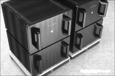
That black sandwich box is soldered on the main board that connects to the TO-3 Motorolas, which are mounted on the heatsink flanges, 2 rows of 12 TO-3s per channel.
The Models 1, 3, 5 and 7 all had the same layout with the lunch box.
You could unsolder the encapsulated gain module and check to see if it is undamaged, there's no way to repair it.
jacco vermeulen said:The front-end of the all-discrete 80's models is in a flat plastic box with round edges, resin-filled.
That black sandwich box is soldered on the main board that connects to the TO-3 Motorolas, which are mounted on the heatsink flanges, 2 rows of 12 TO-3s per channel.
The Models 1, 3, 5 and 7 all had the same layout with the lunch box.
You could unsolder the encapsulated gain module and check to see if it is undamaged, there's no way to repair it.
So essentially if those modules are toast the amps are boatanchors?
I'm not sure it would be worth the investment of a new module.
But the chassis could still be put to good use.
Yep, basically that's the idea but i don't want to be the one with the advice to hack up such beauties.
If you know where to look/ask, there are contemporary designs available that suit the chassis and powersupply of the Model 7 very well.
(the toroid in the Model 7 is a 2400VA monster, IIRC)
If you know where to look/ask, there are contemporary designs available that suit the chassis and powersupply of the Model 7 very well.
(the toroid in the Model 7 is a 2400VA monster, IIRC)
jacco vermeulen said:Yep, basically that's the idea but i don't want to be the one with the advice to hack up such beauties.
If you know where to look/ask, there are contemporary designs available that suit the chassis and powersupply of the Model 8 very well.
(the toroid in the Model 7 is a 2400VA monster, IIRC)
That's really unfortunate.
Surely there is nothing special going on inside those modules?
Maybe it's worth un-potting them and designing a new front end?
So where would you suggest I ask about a contemporary design that would make use of these nice chassis and power supplies?
Thanks!
I own a Rowland Synergy II in which the remote control stopped working many years ago. I can live with this or fix it in some creative way e.g. with a model plane radio control, not that hard.
There are many options if you want to reuse the chassis etc.
Aussie amplifiers? Ground Sound? Or this:
http://www.shine7.com/audio/bpa300.htm
BTW, someone in Hong Kong provided a schematic (and a kit) of what was said to be an early Rowland power amp. I kept it for a while but probably trow it away as I decided to go in a different direction. From memory it wasn´t a particularly complicated construction. Medium I would say.
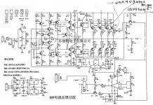
georgehifi said:This may help
Thanks George!
I'm sure that schematic will come in handy!
")
?? why? it is not the correct modelThis may help
OK - this was quite awhile ago and I may be remembering a different model the 3s perhaps but I think the models were all similar.
The ones I worked on were as follows:
The 'front end' was encapsulated, metal case if my memory serves, and plugged into the main board - and the outputs and I believe bias section were on the main board - though if the 7 has TO3s this might be a little different ie not attached to the 'main board', I just don't remember the inside of the 7. The ones I worked on did NOT have the output section linked to in "This may help". But the output section would be easy to figure out given reasonable skills.
If it is just bad outputs should not be to hard to fix - if it involves the front end it is either much more complicated or more expensive. I do not know what the outputs the 7s used - never had to replace any. In fact I don't remember replacing any outputs, just installing upgraded front end modules, and I think one bad module and of course rebiasing the amps.
One could always build a new front end, but I suspect if one had the skills one would not be asking these questions, no slight intended.
A great chassis for a serious DIY amp if it is not rebuildable.
To see a picture of try google or http://www.jeffrowland.com/ClassicAmps.htm
As the model 9 superceded the model 7 it is likely that front end may be the same, as the model 9 also apparently had encapsulated front end.
A lot of manufacturers keep the same circuits topology from model to model with a changes in rail volts power supply size, output transistor numbers and cosmetics.
This is why I said this may help. If it doesn't, no problem everyone get's another circuit to file away in their stash.
Cheers George
A lot of manufacturers keep the same circuits topology from model to model with a changes in rail volts power supply size, output transistor numbers and cosmetics.
This is why I said this may help. If it doesn't, no problem everyone get's another circuit to file away in their stash.
Cheers George
I had the Model 2 amp and Consonance Pre. Both had the potted modules.
And I LOVED both!
I called JRDG about the 5 pin din socket and a remote turn on and Mr. Rowland himself helped me out.
From my discussion with him I would not expect to get the official schematics.
The products sound VERY good, are well built and well worth having repaired. IN MY OPINION.
And I LOVED both!
I called JRDG about the 5 pin din socket and a remote turn on and Mr. Rowland himself helped me out.
From my discussion with him I would not expect to get the official schematics.
The products sound VERY good, are well built and well worth having repaired. IN MY OPINION.
The module is not soldered in on the Model 7s I had open.
I spent an afternoon with Jeff Rowland discussing amplifier designs, changing the modules out to the 'T' version, replacing the screws on the MJ150024/25 outputs with non-magnetic types. We also listened to some 10 meter Cardas balanced interconnects that really sounded good.
You shouldn't need a schematic to repair the output stage.
- Status
- This old topic is closed. If you want to reopen this topic, contact a moderator using the "Report Post" button.
- Home
- Amplifiers
- Solid State
- Rowland Research Amplifier Help!