jacco vermeulen said:Sigh, at least i'm better at lifting a Model 7 couple than Dennis.
(makes ya wonder if there's anything he hasn't worked on)
Oh well, back to playing dumb and posting pretty love handle pics.
Interesting...the pair I am looking at are the same finish but MUCH earlier timeframe.
I believe that the Model 7 went through 3 series revisions over it's lifetime and this pair is the earliest.
In fact, it looks to me like this pair is part of THE earliest edition as there are no potted modules anywhere on them.
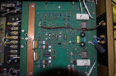
The input circuit is clear to see on one large PCB which is mounted on top of the main filter caps.
Not exactly an arrangement I would go with, but at least performing some diagnosis on the bad unit won't be difficult.
A basic schematic will be easy to draw up.
The power supplies are increadibly massive and there is a separate turn-on circuit PCB with HUGE relays to apply AC.
From looking at the burn marks (2 areas) on the underside of the chassis top plate it looks like the bias resistors on one NPN and one PNP output device gave up their lives.
If there is interest here I will take some photos as I dig deeper into these beasts.
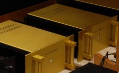
The chassis are in pretty good shape but will need some clean up.
Anyone out there with a good method of cleaning brushed aluminum with gold anodizing?
What about removing scratches and gouges?
")
I unfortunately have not had much time to look into the non-functional monoblock.
I did have some time to look into a few things:
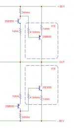
The output stage uses 10 pcs each of NEC 2SD555/2SB600 in TO3 cases, 1ohm Ohmite emitter resistors and a single NEC 2SD555 or 2SB600 as a driver mounted on the common heatsink rails as the output devices themselves. The driver for the NPN output devices is a PNP and vis versa.
The amplifier has three separate power supplies with their own transformers, one for the soft start circuit, one for the input and pre-driver stages, and the massive main output stage supply which has two potted toroids (at least 800va each) and 6 x 21000uF, 100V supply caps.
The good news here is that the main supply can be easily disconnected along with the driver/output stages while having the complete input stage powered up and running.
I'll start signal tracing and measuring the driver and output devices on Monday.
If I do happen to find any damaged output devices, what is the best course of repair?
The original devices are probably unobtainium and I'm wondering if a few replacement devices will work along side the originals?
Otherwise it might be an expensive proposition to replace all 20 output devices with new equivalents but there is always the possibility that new devices will sound better!
Any input is appreciated!
I did have some time to look into a few things:
The output stage uses 10 pcs each of NEC 2SD555/2SB600 in TO3 cases, 1ohm Ohmite emitter resistors and a single NEC 2SD555 or 2SB600 as a driver mounted on the common heatsink rails as the output devices themselves. The driver for the NPN output devices is a PNP and vis versa.
The amplifier has three separate power supplies with their own transformers, one for the soft start circuit, one for the input and pre-driver stages, and the massive main output stage supply which has two potted toroids (at least 800va each) and 6 x 21000uF, 100V supply caps.
The good news here is that the main supply can be easily disconnected along with the driver/output stages while having the complete input stage powered up and running.
I'll start signal tracing and measuring the driver and output devices on Monday.
If I do happen to find any damaged output devices, what is the best course of repair?
The original devices are probably unobtainium and I'm wondering if a few replacement devices will work along side the originals?
Otherwise it might be an expensive proposition to replace all 20 output devices with new equivalents but there is always the possibility that new devices will sound better!
Any input is appreciated!
Old Crest PA power amps use the D555/B600 devices. and in those amps, when one output devices blows, THEY ALL BLOW! making them very expensive to repair. And those devices are no longer made (as far as i know) so finding replacements and enough replacements to get them matched is a pretty big challenge!!!
Those devices have been used in many things and some really good sounding amps too! they just seem to be a bit touchy. a shorted speaker cable even for a half second can blow an amp to pieces so who knows what happened.
The first thing i would do is a check all the output devices for shorts. If you find devices that are shorted then check the emitter resistors. they will most likely be blown too. good idea to replace them even if they aren't blown. and don't replace just the bad ones. replace them all so they match if you can't find exact matches to the factory resistors.
If you find only a couple of blown outputs, you might then be able to construct a matcher ALA PassDIY and use the remaining good devices to try and find matches out of a few new devices. or at least figure out the matching tolerance etc.
The potted module....well....Buy your self a nice Dremel tool and one of those multi piece accessory kits and start grinding. a careful hand and a lot of patients will get that potting material off enough to see whats in there and test for dead devices.
Please don't kill those amps. fix them, fix them correctly and let them live. I just HATE seeing beautiful classic Items hacked up for some cheap project!
or, spend the money, ship them back and have them fixed.
there worth it.
Thats my .02cents anyway.
Zc
Zero Cool said:The potted module....well....Buy your self a nice Dremel tool and one of those multi piece accessory kits and start grinding. a careful hand and a lot of patients will get that potting material off enough to see whats in there and test for dead devices.
Please don't kill those amps. fix them, fix them correctly and let them live. I just HATE seeing beautiful classic Items hacked up for some cheap project!
or, spend the money, ship them back and have them fixed.
there worth it.
Thanks Zc,
Luckily this is one of the earliest series and hence no potted modules! The input and pre-driver stages are on one large PCB with everything easy to see!
My first plan of attack is to check all of the output devices and the drivers for functionality.
As you will see in my earlier post, two of the emitter resistors were completely torched with commensurate burn marks on the chassis lid!
I suspect that the corresponding devices are done.
And I agree with you...since one of the monoblocks is completely functional it makes sense to fix this one. Spending a few $$$ to get them up and running is worth it, particularly as that very expensive power supply is still working perfectly.
Heck, if I get it alive again I might strip both down and have the chassis parts, handles, and heatsinks professionally re-anodized to make them look new.
May be of use if you have to replace obsolete transistors. Please check pin configuration though. The NTE replacements semiconductors are not cheap here in Sweden but the book or CD has been useful to me.
http://secure.mcminone.com/product/EL01-014
http://secure.mcminone.com/product/EL01-014
NTE components are NOT a good choice as you are not getting an exact replacement. one part number can cross reference to many different parts. You could buy 20 of the same NTE part and have many different transistor dies inside the parts. specs can be wildly different. avoid them like the plague!!!
the only NTE branded anything i would use is there resistors which are merely repackaged parts MFG by someone else. and even then i use them only as a last resort!
NTE transistors do work well in guitar distortion boxes however ;0
Zc
the only NTE branded anything i would use is there resistors which are merely repackaged parts MFG by someone else. and even then i use them only as a last resort!
NTE transistors do work well in guitar distortion boxes however ;0
Zc
Well, it´s always possible to measure transistors and not everyone is that negative to NTE. Using replacements with some "critical mind" have helped me and some information on the devices provided it´s technically correct can be useful. It has been so to me.
Their resistors? How come?
Their resistors? How come?
what Rowland amp is this from?
doesn't look at all "Rowland-like"
mlloyd1
doesn't look at all "Rowland-like"
mlloyd1
ungie said:Photo of the main PCB, for those interested!
mlloyd1 said:what Rowland amp is this from?
doesn't look at all "Rowland-like"
mlloyd1
Original first version Model 7 monoblocks.
These guys are likely 20 years old.
OK, I have fired up everything with the output stage disconnected all is working correctly.
I have pulled the driver and output devices and there are a couple on each rail that are bad and their respective emitter resistors are also toast.
For a quick check on the functionality of the amp, is it safe to run the output stages with the bad transistors removed, i.e. with only 8 output devices running per rail?
If this is not recommended, what is the best plan of attack for determining good substitutes (2SD555/2SB600)?
And an earlier question still lingers: Can I replace only the bad devices or will there be matching issues?
If I go nuts and replace ALL of the ouput devices do they require matching?
Thanks for your help.
Oh, Jacco, send me an e-mail and let me know what photos you would like to see and I will send them along!
Can you use the output section with the blown transistors removed? I guess you can if you intend to use loudspeakers that are a rather easy load , don´t dip that much and aren´t current hungry. But a justified question remains; what made the amp brake in the first event?
Matching is a good thing with many devices sharing the job. But the one Ohm emitter resistors do a part of this job. With no matching there is the risk of higher distortion at least. NFB can´t cure everything,
It´s possible that with time the once matched output devices have become different and this may be a problem to solve?
But it´s possible to do some measurements like an easy hfe one.
Or at least check the quiescent current for each device.
I have run amps with devices removed without problems. KEEPING things in mind.
1- class AB amps only. switching rails amps are another issue.
2- Output devices only. drivers have to be there.
3- its for testing only.
4- run without a load.
5- dont even try and full power test or even a short time higher then a couple watts test.
6- i remove enough devices + & - so at least the sides are balanced. IE: if 2 + side devices are bad and only 1 - side device. i remove an extra neg side device so the pairs are even. Probably unnecessary but i do it anyway.
I usually only run the amp for a short period of time as such just long enough to make sure it runs without other problems and that the signal looks clean etc.
Some possible notes.
I recognize the board shown as an older version (from having one open in the early 80s).
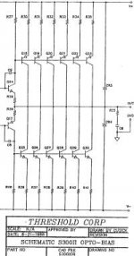
The one I worked on was different, it was a trade show sample and was being upgraded to the latest revision by Jeff and his tech (circa 89). This one ran the output stage open loop (similar to the Threshold refered to above.
I think these do require matching of the devices for lowest distortion (since they have no global feedback). For an 'easy load' you might be able to get away with running less than the full ampount of outputs, and I like zero's suggestion of pulling them in pairs (one N, one P).
If I were to relplace these I would chose the MJ2119X series as the closest TO-3 devices to the hard-to-find 2SB/2SD parts.
Side note:
The last batch of 2SD555 I recieved were fakes.
I recognize the board shown as an older version (from having one open in the early 80s).
The one I worked on was different, it was a trade show sample and was being upgraded to the latest revision by Jeff and his tech (circa 89). This one ran the output stage open loop (similar to the Threshold refered to above.
I think these do require matching of the devices for lowest distortion (since they have no global feedback). For an 'easy load' you might be able to get away with running less than the full ampount of outputs, and I like zero's suggestion of pulling them in pairs (one N, one P).
If I were to relplace these I would chose the MJ2119X series as the closest TO-3 devices to the hard-to-find 2SB/2SD parts.
Side note:
The last batch of 2SD555 I recieved were fakes.
djk said:
If I were to relplace these I would chose the MJ2119X series as the closest TO-3 devices to the hard-to-find 2SB/2SD parts.
Thanks djk!
Do you know of a good source for the MJ21193/4/5/6 devices?
A quick internet search shows availability only in lots of 100 or 300 pcs!
What sort of matching is really necessary here assuming the devices are from the same lot?
My assumption is that the 1R emitter resistors should ensure reasonable current sharing between the paralleled devices.
Of course I could be wrong!
- Status
- This old topic is closed. If you want to reopen this topic, contact a moderator using the "Report Post" button.
- Home
- Amplifiers
- Solid State
- Rowland Research Amplifier Help!