I am trying to build two separate line-level power supplies that share the same transformer 15VAC secondaries. Each PS has two bridges, one for each secondary, with two identical smoothing and regulating circuits that are combined to create the +/G/- output (so I can use low noise LT1086 regs). The two PS grounds are combined at the star point. The only difference between the two PS is that one produces +/- 15VDC with a single set of regulators, and the other produces +/- 10VDC with two sets of regulators in series (not tracking).
Here is the strange part. With the 15V PS disconnected from the secondaries, the 10V PS measures a perfect +/- 10VDC. BUT, with the 15V PS connected, the 10V PS measures +10V/-14V. The 15V PS always measures the correct +/- 15V whether the 10V PS is connected or not (when I tried a tracking configuration with the 10V PS, the voltages were even more strange).
Can anyone explain this? Why would the double-regulated circuit measure differently when the second PS is connected, but the single reg circuit is unaffected? How can I do this so both work together with the correct voltages?
Thanks in advance for the help!
Attachments
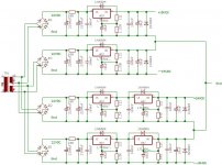
are your rectifiers drawn wrong or wired wrong?
The 16.7V between the pairs of regulators may be a little too high for worst case conditions. This should not be the cause of your current problem but I would reduce the 1k5 to 1k36 or 1k4.
Similarly, I would increase the caps on the lower regulator resistor from 10uF to 100uF/220uF.
What is the minimum current draw on the 1086?
does 121r draw sufficient current to ensure that the reg is operating correctly.
What happens to the voltages if you add some dummy loads to each of the reg outputs?
Is there any ringing or oscillation on any of the regulator outputs?
The rCRC at the input of the regulators will contaminate the sense currents/voltages on the later stages of the ground/return wires/traces.
All of the 2200uF caps must be returned to the central PSU ground, so that any pulsing from these caps is kept separate from the ground/sense lines.
Similarly, the 4 Zero Volt lines should be separately returned to the central PSU ground.
NO YOU CANT DO THAT!
You can't common two post-regulator voltages (your negative rails) if they are a different voltages, because they share the same transformer windings. The two regulators are fighting each other over what the 'ground' votage ought to be.
Either you need four transformer windings, or use proper negative rail regulators like the LM337.
Aah,Steerpike said:NO YOU CANT DO THAT!
You can't common two post-regulator voltages (your negative rails) if they are a different voltages, because they share the same transformer windings. The two regulators are fighting each other over what the 'ground' votage ought to be.
Either you need four transformer windings, or use proper negative rail regulators like the LM337.
the -10V line gets fed through the diode of the rectifier from the -15V line! giving ~14.3V
- Status
- This old topic is closed. If you want to reopen this topic, contact a moderator using the "Report Post" button.
- Home
- Amplifiers
- Solid State
- Strange Power Supply Behavior