Mooly said:I'll post some more info later today")
Thanks!
Hi Tibi,
I have put a few notes together, in no particular order, that hopefully may help.
If you are serious of having a go I can provide help via this forum or you can email me. Maybe some others will have a bash as well.
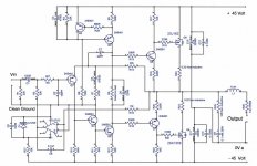
You say you use a -/+50 volt supply. That should be OK, but if it's any higher we may have to look at replacing Q5 with something slightly higher rated.
The circuit has "two R8's" . These are so a fixed value of resistor can be fitted to set the standing current in the output stage. R 8 is initially replaced with a 470 ohm preset to adjust, then the preset is measured and a suitable fixed value fitted.
The TL071 can not be substituted. It's not in the audio path, but you will see it uses only a single negative supply. That's why you can't use anything here.
Note the polarity of C1 and C3.
R18/21 must be on the gates of the FET's if these are wired to the PCB.
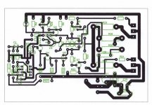
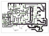
The output inductor is not on the PCB. In the majority of cases it's not even needed, the 0.22 ohm provides enough isolation to prevent any stability issues.
Grounds, there are two on the PCB. Grounding is usually where it all goes wrong on DIY designs. We don't make it easy for ourselfs by building amps on separate boards but with care very good performance is achievable.
R25, the zobel resistor should be a 2 watt carbon type. Must not be inductive !
D1, the zener for the OpAmp can be a 12 volt 0.4 or 1.3 watt type.
I have put a few notes together, in no particular order, that hopefully may help.
If you are serious of having a go I can provide help via this forum or you can email me. Maybe some others will have a bash as well.
You say you use a -/+50 volt supply. That should be OK, but if it's any higher we may have to look at replacing Q5 with something slightly higher rated.
The circuit has "two R8's" . These are so a fixed value of resistor can be fitted to set the standing current in the output stage. R 8 is initially replaced with a 470 ohm preset to adjust, then the preset is measured and a suitable fixed value fitted.
The TL071 can not be substituted. It's not in the audio path, but you will see it uses only a single negative supply. That's why you can't use anything here.
Note the polarity of C1 and C3.
R18/21 must be on the gates of the FET's if these are wired to the PCB.
The output inductor is not on the PCB. In the majority of cases it's not even needed, the 0.22 ohm provides enough isolation to prevent any stability issues.
Grounds, there are two on the PCB. Grounding is usually where it all goes wrong on DIY designs. We don't make it easy for ourselfs by building amps on separate boards but with care very good performance is achievable.
R25, the zobel resistor should be a 2 watt carbon type. Must not be inductive !
D1, the zener for the OpAmp can be a 12 volt 0.4 or 1.3 watt type.
Attachments
Tibi,
I would recommend building the boards up without the FET's connected at all initially. For the first power up you can replace R8 with a link. Only when we know it's working properly do we connect the FET's and adjust the current.
I will draw tommorrow how to connect it all up.
I would recommend building the boards up without the FET's connected at all initially. For the first power up you can replace R8 with a link. Only when we know it's working properly do we connect the FET's and adjust the current.
I will draw tommorrow how to connect it all up.
Mooly said:How's it going Tibi. Are you winning
Good so far!
I etched and drilled the PCB this weekend.
Just got the missing parts and I'll put it together this afternoon.
I have a question, for R23 & R24 (0.22R non inductive) I only found 0.33 non inductive ones or 0.22 regular ceramic, would the 0.33 ones work?
Also could you please give me some pointers on how to set the bias?
Thanks!
Hi Tibi,
0.33 ohm should be fine. For the first power up have R8 shorted out, and do not connect the FET's at all. Have nothing connected to the output -- only the DVM.
If all's well the output of the amp will settle to zero volts.
The output of the OpAmp should be around -7 volts or so. Check the supply to the IC is at -12.
There should be virtually no voltage across R17 and R22 the 1K5's and there should be 0.7 volts across R5 the 100 ohm.
You can then replace R8 with a 470 ohm ( or 1K ) preset. Start with it at zero ohms. Turning this will cause the voltage across the 1K5 to increase. Note that without the FET's the volt drop over each will not be equal.
If all that is OK it's time to connect the FET's but first turn the preset back to zero ohms ( no voltage over the 1K5's )
Power up and check the output voltage again, should be 0.00 volts. If thats OK slowly adjust the pot to give around 100 ma through the FET's. Thats 33 mv across each 0.33 ohm you know that.
Edit -- Always worth powering up with a 100 watt bulb in series with the mains.
0.33 ohm should be fine. For the first power up have R8 shorted out, and do not connect the FET's at all. Have nothing connected to the output -- only the DVM.
If all's well the output of the amp will settle to zero volts.
The output of the OpAmp should be around -7 volts or so. Check the supply to the IC is at -12.
There should be virtually no voltage across R17 and R22 the 1K5's and there should be 0.7 volts across R5 the 100 ohm.
You can then replace R8 with a 470 ohm ( or 1K ) preset. Start with it at zero ohms. Turning this will cause the voltage across the 1K5 to increase. Note that without the FET's the volt drop over each will not be equal.
If all that is OK it's time to connect the FET's but first turn the preset back to zero ohms ( no voltage over the 1K5's )
Power up and check the output voltage again, should be 0.00 volts. If thats OK slowly adjust the pot to give around 100 ma through the FET's. Thats 33 mv across each 0.33 ohm
you know that.Edit -- Always worth powering up with a 100 watt bulb in series with the mains.
Mooly said:Hi Tibi,
0.33 ohm should be fine. For the first power up have R8 shorted out, and do not connect the FET's at all. Have nothing connected to the output -- only the DVM.
If all's well the output of the amp will settle to zero volts.
The output of the OpAmp should be around -7 volts or so. Check the supply to the IC is at -12.
There should be virtually no voltage across R17 and R22 the 1K5's and there should be 0.7 volts across R5 the 100 ohm.
You can then replace R8 with a 470 ohm ( or 1K ) preset. Start with it at zero ohms. Turning this will cause the voltage across the 1K5 to increase. Note that without the FET's the volt drop over each will not be equal.
If all that is OK it's time to connect the FET's but first turn the preset back to zero ohms ( no voltage over the 1K5's )
Power up and check the output voltage again, should be 0.00 volts. If thats OK slowly adjust the pot to give around 100 ma through the FET's. Thats 33 mv across each 0.33 ohm
Edit -- Always worth powering up with a 100 watt bulb in series with the mains.
I just powered it up, however I'm reading 312 mV across R17, nothing across R22
Hi Tibi,
That sounds OK. Whats the DC voltage on the output, junction of R23/24 ( take it the FET's are not in yet ). That should be zero to within a millivolt or so.
Have you got a pot in for R8 ? If not that's the next step. Make sure that PSU is fully discharged before working on anything
That sounds OK. Whats the DC voltage on the output, junction of R23/24 ( take it the FET's are not in yet ). That should be zero to within a millivolt or so.
Have you got a pot in for R8 ? If not that's the next step. Make sure that PSU is fully discharged before working on anything
Mooly said:Hi Tibi,
That sounds OK. Whats the DC voltage on the output, junction of R23/24 ( take it the FET's are not in yet ). That should be zero to within a millivolt or so.
Have you got a pot in for R8 ? If not that's the next step. Make sure that PSU is fully discharged before working on anything
Phew!
I read 0V AC/0V DC on the output, no, the FETs are not connected yet, R8 is just a link right now, I have a 5k pot ready, I'll just have to solder it in place.
I'll keep you updated.
Thanks!
A 5 k pot is too high, you will never adjust it finely enough. If you do try it be careful and start with it at zero ohms, just be careful.
Again run it up without the FET's. Adjusting the pot will cause the voltage across R 17/22 to increase ( still unequally ). If the FET's were in they would begin to conduct around 3 volts or so.
Next step, turn it back to zero ohms and connect the FET's.
Remember the output is taken from the Drains, the Source goes to the rails.
Tweak the pot to give around 80 to 100 ma flowing in the FET's ( 33mv across each 0.33 ohm ) and thats it hopefully.
Well not quite Switch off and measure the pot out of circuit and then fit a resistor for R8 ( get as close as you can with a parallel pair ).
One other thing -- the output take a few seconds to settle to zero so a relay in the output required--- no problem I can draw something very simple that will work. For now connect the speaker AFTER switching on the amp and disconnect before switching off.
Again run it up without the FET's. Adjusting the pot will cause the voltage across R 17/22 to increase ( still unequally ). If the FET's were in they would begin to conduct around 3 volts or so.
Next step, turn it back to zero ohms and connect the FET's.
Remember the output is taken from the Drains, the Source goes to the rails.
Tweak the pot to give around 80 to 100 ma flowing in the FET's ( 33mv across each 0.33 ohm ) and thats it hopefully.
Well not quite
Switch off and measure the pot out of circuit and then fit a resistor for R8 ( get as close as you can with a parallel pair ).One other thing -- the output take a few seconds to settle to zero so a relay in the output required--- no problem I can draw something very simple that will work. For now connect the speaker AFTER switching on the amp and disconnect before switching off.
- Status
- This old topic is closed. If you want to reopen this topic, contact a moderator using the "Report Post" button.
- Home
- Amplifiers
- Solid State
- please help with an oscillating amp