I'm working on a Hafler P-230 and I'm having trouble finding information on it. One channel was destroyed, had a serious melt down, and I wanted to build the PC-19 boards with good quality components.
I see the PC-19 is also used in the DH-220, but I don't know if the schematics are exactly the same since the 230 uses 6 MOS-FETS and the 220 uses 4.
I am also wondering if there are any good upgrades or changes in design to make the amplifier sound and work better.
Thanks,
JT
I see the PC-19 is also used in the DH-220, but I don't know if the schematics are exactly the same since the 230 uses 6 MOS-FETS and the 220 uses 4.
I am also wondering if there are any good upgrades or changes in design to make the amplifier sound and work better.
Thanks,
JT
There are no differences between the P230 and DH220 amps except for the extra pair of mosfets, and the heavier duty power cord.
The PC19 card was a result of the various mods that people normally did to the DH200 circuit. As a result, there isn't much you can add to the PC19 cards. If you are going to start from scratch with blank PC19 PCB's use good quality parts and you will be good to go.
The PC19 card was a result of the various mods that people normally did to the DH200 circuit. As a result, there isn't much you can add to the PC19 cards. If you are going to start from scratch with blank PC19 PCB's use good quality parts and you will be good to go.
I must say that I have been really impressed with Exicon and Profusion. They were easy to order from, quick, and really weren't that expensive.
I've always been afraid of getting ripped off on the transistors. So, I think I might stick with the Exicon Mosfets.
The schematic for the Hafler uses capacitors to match gate capacitance, should I change the numbers of the caps to match the different transistors? I haven't looked at the specs closely, but any ideas or help on that front?
I am sorry to give you some possible bad news. The 3 N-channel devices on each channel must be matched on Vgs to within ±10%. Ditto for the P-channel devices.
The numbers on the MOSFETs in Hafler amps reflect their grading (1-7) of their Vgs. You need matched triplets for the P-230.
I have used Exicons, etc., with no apparent change in sound but, again, they must be used in matched pairs (or triplets) and not mixed in with Hitachi devices.
Do you really need to replace MOSFETs? They are very rugged and rarely fail. Also, you can always use your amp with just a pair of N-channel/P-channel devices instead of a triplet. Heck, you could even use it with just one N/P-channel per side if needed -- after you reset the bias accordingly.
Might be simpler to just put some low ohm resistors eg 0.22R 3W in the drains and have done with it. The lost power wont be much of a loss in a domestic amp.
Feel free to tell me i'm a moron") but it would save a hell of a lot of cost (the mosfets are expensive) for very little loss.
but it would save a hell of a lot of cost (the mosfets are expensive) for very little loss.
Feel free to tell me i'm a moron
but it would save a hell of a lot of cost (the mosfets are expensive) for very little loss.jaycee said:Might be simpler to just put some low ohm resistors eg 0.22R 3W in the drains and have done with it. The lost power wont be much of a loss in a domestic amp.
Feel free to tell me i'm a moron
By no means am I going to call you a moron.
I am just curious of why you would put the resistors there? So the output from each one is more balanced or something?
The resistors make the mosfets share the load. In the Hafler factory, this was obtained by matching the output devices so the characteristics were similar. This basically meant having a load of them, and testing them individually to see how well they matched. To get a good set of matched pairs you'd have to buy 25 of each device at least.
Most amps have such resistors anyway, so it is not such a big deal.
If the devices are not made to share, and not matched, then one of them ends up doing more work than the others. This can lead to device failure.
Most amps have such resistors anyway, so it is not such a big deal.
If the devices are not made to share, and not matched, then one of them ends up doing more work than the others. This can lead to device failure.
jaycee said:The resistors make the mosfets share the load. In the Hafler factory, this was obtained by matching the output devices so the characteristics were similar. This basically meant having a load of them, and testing them individually to see how well they matched. To get a good set of matched pairs you'd have to buy 25 of each device at least.
Most amps have such resistors anyway, so it is not such a big deal.
If the devices are not made to share, and not matched, then one of them ends up doing more work than the others. This can lead to device failure.
Great thanks, I was under the impression that you didn't need to put resistors on the 'output' side of the MOSFETS, but what you said makes sense. With the price of MOSFETS it wouldn't be fun buying 25 or so.
What is a good way to match them, just for future knowledge?
joetama said:What is a good way to match them, just for future knowledge?
http://www.passdiy.com/pdf/matching.pdf
-Aaron,
The matching write up by Pass referenced by jaycee is for Vertical MOSFETs, not the Lateral MOSFETs used in your amp. These two different types of MOSFETs have different electrical properties therefore Pass's matching device probably needs modification to properly measure your Laterals.
I don't know the exact changes needed but this has been discussed before at DIYaudio. A search should turn up how to redesign the Pass procedure for your Lateral MOSFETs.
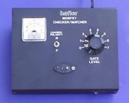
I never learned the differences as I use an original bona fide Hafler matching device (see below).
Some say that MOSFETs with the same batch code will match very well. I recently measured 12 J-49 devices and found a very wide variation of Vgs amongst those with the same batch code.
But, in reference to my earlier question, how do you know you need replacement MOSFETs?
The matching write up by Pass referenced by jaycee is for Vertical MOSFETs, not the Lateral MOSFETs used in your amp. These two different types of MOSFETs have different electrical properties therefore Pass's matching device probably needs modification to properly measure your Laterals.
I don't know the exact changes needed but this has been discussed before at DIYaudio. A search should turn up how to redesign the Pass procedure for your Lateral MOSFETs.
I never learned the differences as I use an original bona fide Hafler matching device (see below).
Some say that MOSFETs with the same batch code will match very well. I recently measured 12 J-49 devices and found a very wide variation of Vgs amongst those with the same batch code.
But, in reference to my earlier question, how do you know you need replacement MOSFETs?
Attachments
Dick,
Thanks for the information, that Hafler tester looks like a handy piece of equipment.
The reason I need new mosfets is because when the amplifier channel decided to double as an easy bake oven my grandfather removed the mosfets to use in another amp.
He probably has them hidden in his basement somewhere, but who knows. It is like a vintage radio and audio trash heap down there in places...
I really don't see much difference between the K150/J50 and the K149/J49 except for voltage maximum.
Maybe someone could correct me if I am wrong.
If I was to use the higher voltage transistors could I also increase the rail voltage with a new transformer & caps? Or would that be a bad idea since the +/- voltage would also increase to the driver boards and the transistors would need a higher peak voltage to output more power anyway (which is the point of the higher rail voltage)?
You could boost the rails voltages of your P-230. If you study closely the schematics of the P-230 and DH-500 you can see the DH-500 uses the same exact circuit card, except for two small resistors on either side of the DC nulling pot. So, you could boost the rails voltages but the amp would need more heat sinking to handle the increased output. So, boosting rails voltages is not worth the effort.
The original Hitachi MOSFETs came in several different voltage levels, as Stormrider pointed out. The 2SJ48/49/50 series is rated at 120/140/160 on Vds (drain to source voltage). They are backwards compatible. Ditto for the 2SK133/134/135 series.
Now, about where to place series resistors to balance the current demands of mis-matched output devices. I am looking at an amp schematic in the original Hitachi Power MOS FET Data Book. The P-230's output topology is, I believe, what is called a "source follower." The device drains are attached directly to the power supply rails. The source side of the devices are daisy chained together and attached to eyelets at the bottom of the circuit card. All outputs from the sources are connected to a common point that provides the output that goes to the speakers. The circuit in the Hitachi hand book shows balancing resistors in series with the sources, between the source outputs and the common connection point that provides speaker connections. The resistors listed are .22 ohms.
As jaycee pointed out, to get matched sets you might have to go through 25 or so devices, which makes getting matched triplets expensive. For testing purposes you could borrow a pair of devices from the good channel. Run it with 4 devices and use the 2 borrowed ones to get the repaired channel up and running. Then, when all is well, you could begin a search for matched triplets. I can sell you 3 matched 2SJ devices. Others, such as Bear who posts here, may have 3 matched 2SK devices to sell. Also, depending on the grade numbers of your present 2SK devices, I might be able to provide a match of one or two of them which means you might get your amp running with 4 devices per channel or maybe even 6 devices per channel.
So, you have options.
Hitachi Datasheets
http://www.bonavolta.ch/hobby/files/2SK135.pdf
covers K133, 134, and 135
http://www.bonavolta.ch/hobby/files/2SJ50.pdf
covers J48, 49, and 50
http://www.bonavolta.ch/hobby/files/2SK135.pdf
covers K133, 134, and 135
http://www.bonavolta.ch/hobby/files/2SJ50.pdf
covers J48, 49, and 50
"The circuit in the Hitachi hand book shows balancing resistors in series with the sources, between the source outputs and the common connection point that provides speaker connections. The resistors listed are .22 ohms."
Yes, resistors in the sources is correct. They should be low inductance types. I wonder though if it will help that much. Current sharing at higher currents can't realistically be a problem with laterals, it's if you want the idle current shared equally you need to match. I don't know if 0.22 ohms is really enough, as the fets have very low transconductance to begin with. (corresponding to a transresistance of over 1 ohm at bias current)
The reason the different voltage parts are identical in all other parameters is probably because they really are the same device and then graded after the production depending on which breakdown voltage the batch got
- Status
- This old topic is closed. If you want to reopen this topic, contact a moderator using the "Report Post" button.
- Home
- Amplifiers
- Solid State
- Hafler P-230 recondition