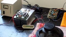
Here you have video i have made hours ago.... HRII rebuilt and listening the unit... the noises you will listen, while the video is reaching the end, are because of the MP3 output plug..contact... damn toy!
http://www.youtube.com/watch?v=9uwMoAXTKX4
......................................................................................................
Had problems?
Post them in this thread.
......................................................................................................
Re visiting the HRII
I am re assembling the unit, and i found that we can make several
mistakes… and some of them will trigger a panic into some folks
not to much experienced building amplifiers.
While adjusting, it is important to have heatsinks installed into the
output transistors and also into the drivers… thermal drift will
made you unable to adjust, and you may lost your output…I have
tested to see what happens.
Be carefull if you gonna use wires to connect your vbe multiplier
(the thermal sensor, the one adjusts the stand by current) or your
output transistors… this starts oscilations…make it as short as
possible. (less than 10 centimeters)… HRII transistors are high
speed, this means it can oscilate into VHF frequencies.
Do not connect your supply voltage without the protective
resistances, those ones in series with your rails.
Do not forget to run a ground wire from the amplifier board
to the heatsink… output transistors must be insulated from
the heatsink as also the thermal sensor (bias adjustment Tr.)
To adjust, or to check your off set and bias, first produce a short
circuit into the input terminals, install protective resistances, and
It is a very good idea to install 47 ohms resistance into the speaker
terminal, and to do that after you check the off set first time if not
high the offset (bigger than 25 milivolts) then.install the output
load (47 ohms) to avoid be fooled by unstabilities… the amplifer
is not so distant from the threshold of oscilation, tuned this way,
amplifiers use to produce a nice treble (non harshing one)… but,
the price you pay is that you may have oscilations if you fail in
something during the construction or installation.
Measuring your stand by current, having your meter connected
into the protective resistance extremes……. opening the short
into the input and introducing your finger (finger-o-matic signal
injector) into the live input, the mains noise will be listened
if you have speaker..if not..your 47 ohms load will be hot.
The voltage you will measure over the protective resistances
must increase when you touch with your finger producing
amplification…but when you release your finger, the current
(voltage readed) must drop down to 400 to 800 milivolts over
10 ohms (for instance)
If injecting signal with your finger, or other signal source, and
them releasing your finger from the input terminal… if doing
that you experience delay to reduce the current, ot if it stays
then ground your heatsink, install speaker into the output and reduce
power transistors wires lengthes, and thermal sensor wire length too
also remove the condenser (if you have it) installed from colector to
emitter into the heat sensor transistor, the bias adjustment unit.
The amplifier was not hard to adjust, was linear the current increasing
while I was turning the trimpot while adjusting bias.. the resistance
i have between driver transistor emitters is 180 ohms…. Was stable,
but I could force unstabilities doing errors, reason why I am publishing
some comments, some tips and tricks.
Into the input i am using bipolar 4.7 uF condenser…. In series with signal
and connected to drivers base, the 470 ohms resistances were substituted
by 100 ohms resistance…I am not using the treble booster..it is switched
off, my speakers, the ones I have now a days, are flat (not to much unflat).
Small details, can drive you mad if you are not skilled into amplifiers
construction…you may feel sad and abandon your unit… having care
with those details I am explaining you gonna be happy and dancing.
Stand by current can go from 40 to 80 miliamperes (400 milivolts to 800
milivolts measured over 10 ohms protective series resistances)… 300 mA
is what you gonna measure having not ground.. do not be scared..install
ground and be happy… you gonna see your crazy current measured drops.
Attachments
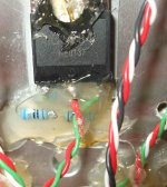
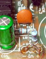
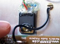
I have installed a big transistor as heat sensor... and
i have fixed the one, insulated, under the board... no trimpot... resitances fixed... 2K2 and 820 ohms.
This is hot glue... it melts bellow 90 degrées... and my amplifiers never reach this temperature... this same glue is fixing my board into the heatsink.
Will melt?... i don't think so.
regards,
Carlos
Attachments
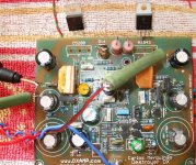
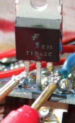
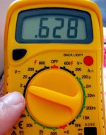
Check VBE into the output transistors... also
do the same with drivers, and also do the same with the voltage amplifier, also into the differential and into the rail regulators.
The voltage must be from 500 to 640 milivolts into the HRII.
But, the best voltage is 575 milivolts.... higher goes to the Vas transistor and 700 milivolts goes to the rail regulators base to emitter voltage.
This voltage is stable, as not drift or offset... and try to clean your probe point... i did it soldering to be sure...also i was observing thermal drift and VBE results.. studying the unit to perceive details to inform.
regards,
Carlos
Attachments
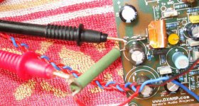
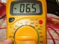
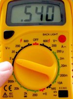
I found this adjustment fine...i could match because of this adjustment
the NPN and PNP output VBEs.
Observe the voltage measured over the protective resistances... this is sligtly different into the positive compared to the negative because into the positive side you have 10 miliamperes only to bias the zener diode you have into the input.
This is divided by 10 ohms (if you use 10 ohms as protective of course) and will result into 60 miliamperes... the unit is fine from 40 to 80 miliamperes... and can operate with lower and higher than that without problems too... this is the suggested range.
regards,
Carlos
Attachments
The heatsink was grounded.. and this is normal, as when
you install the heatsink into the metalic case, the heatsink will be grounded because the metalic case goes to the ground..or.. at least, people use to pick the secondary central wire and attach it into the chassis.
regards,
Carlos
you install the heatsink into the metalic case, the heatsink will be grounded because the metalic case goes to the ground..or.. at least, people use to pick the secondary central wire and attach it into the chassis.
regards,
Carlos
Attachments
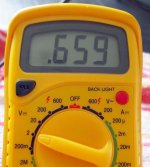
This is the way it is when i made the recording you have the link into the first post
Not the best... i like the most 575 milivolts..but this one is good too.... the driver transistors VBE voltage is around 600 milivolts... bigger than the output... normal that.
regards,
Carlos
Not the best... i like the most 575 milivolts..but this one is good too.... the driver transistors VBE voltage is around 600 milivolts... bigger than the output... normal that.
regards,
Carlos
Attachments

- Status
- This old topic is closed. If you want to reopen this topic, contact a moderator using the "Report Post" button.
- Home
- Amplifiers
- Solid State
- HRII revisiting, have you experienced problems folks?