I own two of these amps that have been a dependable product
that produces a workable sound for its price.
Recently both amps started burning resistors R222 and R268
which activate the dethump relays. Though some burning smell
emanated from the units there was no interruption to their functionality.
I've uprated the power rating on the resistors so far with success.
Has anyone else found this problem and know of the cause, and a cure?
Many thanks in advance,
Lectran
Parallel Resitor Solution
I worked the problem by replacing each 10 ohm 5% 1 W Resistor with 4 x 39 ohm 5% 1 W Resistors in parallel.
These 4 parallel Resitors have brought the impedance back to within the original 10 ohms working tolerance and mean that each 39 ohm Resistor has only 1/4 of the power to dissipate.
Lectran
I worked the problem by replacing each 10 ohm 5% 1 W Resistor with 4 x 39 ohm 5% 1 W Resistors in parallel.
These 4 parallel Resitors have brought the impedance back to within the original 10 ohms working tolerance and mean that each 39 ohm Resistor has only 1/4 of the power to dissipate.
Lectran
Hi Lectran,
These resistors are part of the zobel network. Usually if they overheat it is an indication of a problem. Are you using weird cables or speakers? 1 watt resistors are usually OK in this position.
http://users.tpg.com.au/gerskine/greg/dse a2760 stereo amplifier.htm
regards
These resistors are part of the zobel network. Usually if they overheat it is an indication of a problem. Are you using weird cables or speakers? 1 watt resistors are usually OK in this position.
http://users.tpg.com.au/gerskine/greg/dse a2760 stereo amplifier.htm
regards
Reply
Hi Greg,
Thanks for your reply and for the link to your site.
I previously found your site through Google and very much appreciate the info and images you've provided there.
I'm driving one 8 ohm Speaker per channel in a small hall about 10 metres long. Each Speaker is fed from a figure 8 10 amp speaker cable about 15 metres long.
The Resistors in question are subject to the output voltage swing ...
the larger the swing the more power they dissipate
the smaller the swing the less power they dissipate
because each Resistor and its associated Capacitor integrate the output Voltage.
The only variable that comes to mind is that recent performances
have had a richer harmonic content meaning the amps were pushed harder for the same apparent music level.
If that be the variable then the Resistor/Capacitor integrator worked harder than previously and may simply be under-designed.
The DSE A2760 amp has mediocre performance, but can be substantially improved with a few inexpensive mods - see attached PDF file.
The amp itself is solidly constructed and can still be purchased cheaply on ebay (but not from Dick Smith - long been out of stock!)
The total cost of the mods is less than AU$20.00
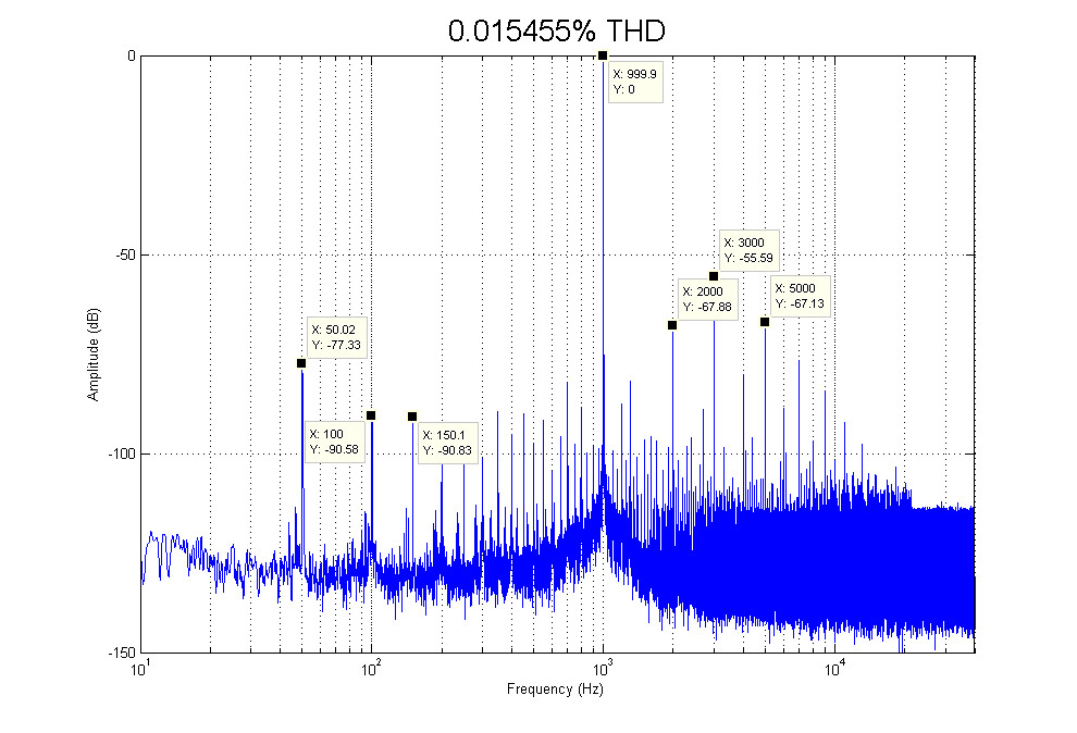
I've also attached THD spectra for the stock and modded amp (LTSpice simulations). In practice, the modded amp sounds very pure - similar to a Class A amp, but runs barely warm.
I have modded two of these amps, and both have been running for more than a year without any problems.
One of the modded amps came 2nd in a recent solid state amp shootout at the NSW Audiophile Society (beating much more expensive amps).
The usual safety precautions should be taken when working on a mains powered device.
The amp itself is solidly constructed and can still be purchased cheaply on ebay (but not from Dick Smith - long been out of stock!)
The total cost of the mods is less than AU$20.00
I've also attached THD spectra for the stock and modded amp (LTSpice simulations). In practice, the modded amp sounds very pure - similar to a Class A amp, but runs barely warm.
I have modded two of these amps, and both have been running for more than a year without any problems.
One of the modded amps came 2nd in a recent solid state amp shootout at the NSW Audiophile Society (beating much more expensive amps).
The usual safety precautions should be taken when working on a mains powered device.
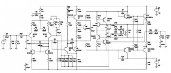
And here's the LTSpice schematic for the modded DSE A2760 amp.
Please note that:
1. The component designations in the attached schematic do not correspond with those used in the Koda schematic.
2. The following SPICE data was used for the LTSpice simulation:
2SC5200 = 2SC3281=MJL3281A
2SA1943 = 2SA1302=MJL1302A
2SA733=BC557
2SC945=BC547
2SC2383=BF446; 2N3700; 2SD1291; KT630G; ECG382; ECG31; D1812
2SA1013=ECG32; BFT19; 2SB1212; 2SA965
2SC227=KT601A; 2SC217; 2SC3420; D826; 2SB492; B492; 2SD2147
2N5551=BC546B; BF391; BC538-16; BCX49;
2N5401=BC526B; BF492; BF491; BF398; BF397
2SD669=2SC1847; 2SB649 (BD139)
2SB649=BD238; 2N6211
Incidentally, simulated THD at 50Wrms/1kHz/8 ohms is approximately 0.001% (and the stock amp has about 0.3% THD under the same conditions).
Attachments
DSE A2760
And here's the (edited) LTSpice library data file with SPICE models for all of the bipolar devices used in the LTSpice schematic for the modded amp that was posted a few days ago.
Unzip the attached "standard.zip" file, then rename "standard.txt" file to "standard.bjt". Overwrite the existing "standard.bjt" file in your LTSpice \lib\cmp folder with the renamed file.
You can then run simulations for the modded amp with LTSpice. Don't forget to turn off compression in LTSpice - click on Tools\Control Panel\Compression and uncheck "Only compress transient analyses", "Enable 1st Order Compression" and "Enable 2nd Order Compression". If this isn't done, the simulation results will be degraded.
Attachments
Thanks for posting details of the modifications, Reszipsa. I recently managed to get my hands on two of these amplifiers (one on hard rubbish and another on e-bay) and was planning to use them as part of a bi-amp active set-up. Just wondering whether you think it's worth modifying these, or am I better off using the cases and p/s etc as the basis of new amps?
Provided the second hand amps you've bought are in (physically) good condition, you should mod them. The cost is minimal if you do the work yourself, and the improvement in performance is quite dramatic.
Alternatively, you could ask Elson Silva to mod the amps for you. He can be contacted through the NSW Audiophile Society.
As the output stage of this amp uses only a single pair of bipolar transistors, I would recommend that it not be used with low sensitivity/low impedance speakers.
Alternatively, you could ask Elson Silva to mod the amps for you. He can be contacted through the NSW Audiophile Society.
As the output stage of this amp uses only a single pair of bipolar transistors, I would recommend that it not be used with low sensitivity/low impedance speakers.
Sorry to bump an old thread.
I've got one of these amps and am aware that changing some caps etc on the board and drastically improve the amp.
Whilst I can solder, i know little about electronics and have no idea which caps etc i should be upgrade and with what.
Is there a guide or could someone explain to me what needs to be changed/why?
Phil")
I've got one of these amps and am aware that changing some caps etc on the board and drastically improve the amp.
Whilst I can solder, i know little about electronics and have no idea which caps etc i should be upgrade and with what.
Is there a guide or could someone explain to me what needs to be changed/why?
Phil
The "what" is in Post #8.
For reference, here's the schematic of the original unit.
Looking at the mods suggested, I'm not sure whether I can agree with all of them.
I'm not sure what the deal with the .22R wirewounds is. Connected as described, you'd end up with a lousy damping factor of only 9 re: 4R (18 re: 8R), which is considerably less than I'd consider acceptable in a "serious" amplifier and would be expected to lead to audible coloration with many a real speaker.
It also seems the intent is to use the unit as a power amp only. If you don't want that, I'd just tweak the preamp feedback network a little for more input headroom (R132/135: 4k7 MF, R139/143: 10k MF, C134/139: 68p ceramic NP0) and be done with it. In the power amp, R230/253 can then retain their original values, save for changing to metal film, and R231/281 should become 47k for lowest DC offset (assuming you do not install the 39k parallel resistor at R238/286 they suggest). You can use a half-watt part for R231/281 if you want to get fancy.
A few more items are mysterious or questionable at best. Why replace R239/287 by noisier 10k units (I'd rather suggest 1k, and 1/4 W will do fine)? Why relocate R238/286 (essentially no functional difference at all)?
The basic ailment of the power amp seems to be that the output transistors are not in the feedback loop (WTF?) and accordingly, there is serious distortion. (Looking at the stock distortion graph, performance is just garbage.) If you do want to include them, extra compensation has to be added for stability (a fancier 2-pole one in this case). They're also adding trimpots for cranking up quiescent current (for even lower distortion at low power) and reducing voltage gain from 36 dB to 26 dB (for use as a "standard" power amp) here.
I guess I'll have to play with the simulation model posted earlier to determine stability and all that good stuff.
Last edited:
The 022R resistors are intended to reduce the damping factor to produce a somewhat "warmer" sound quality. A number of people who have auditioned the modded amp have expressed a preference for the sound in this configuration that with the stock output inductors.
An alternative is to retain the stock inductors and shunt each with a 1R/10W resistor. This prevents degradation of the damping factor and minimises "ringing" with capacitive loads.
All of the suggested mods for the amp were derived from extensive SPICE modelling, even though some may seem inexplicable or even sub-optimal at first blush.
BTW, while the amp is stable with a pair of series-connected 0R22 resistors between the output transistors and the speaker load, the margin of stability may not be very great under certain load conditions.
I therefore recommend that either a 1R/10W resistor be substituted for each series pair of 0R22 resistors (resulting in an even lower damping factor, which may not be subjectively acceptable to some) or that the stock output inductors be left in place and shunted with 1R/10W resistors.
IMO, the preamp section of the amp degrades the sound quality, and should just be bypassed. I suspect that tweaking the preamp's feedback network will be like putting a Band-Aid on a gangrenous leg
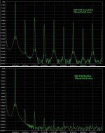
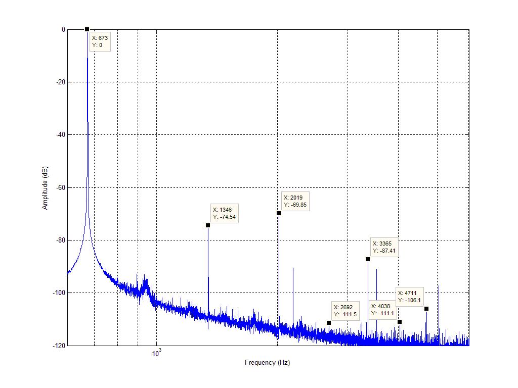
FWIW, here is the measured performance of the power amp (completely standard - no preamp) in one of these amps @ 1W into 8ohm:
1Khz:

667Hz:
My measurement setup is nothing special - USB DAC (TE7022+ES9023) as source, Asus Xonar DX as ADC. If the distortion from the amp disappears below the noise floor after modding i'll be pretty happy
1Khz:
667Hz:
My measurement setup is nothing special - USB DAC (TE7022+ES9023) as source, Asus Xonar DX as ADC. If the distortion from the amp disappears below the noise floor after modding i'll be pretty happy
Complete list of mods I've decided on:
-Replace C206/C224, C207/C231 with Panasonic FC 470uF 63V
-Replace C204/C228 with Panasonic FM 100uF 50V
-Replace C208/C234 with NP 100uF 50V (two series Panasonic FC 220uF 63V connected neg-neg)
-Replace C212/C240, C205/C233 with MKP 4.7uF (Low ESR Polarised Electro is fine for C205/C233, i just have MKP caps on hand already)
-Replace R230/R253 with 3K||2 metal film 1% 0.5W
-Double pole filter, 220pF C0G/100pF C0G/2.2K metal film 1% 0.5W. 100pF to base of V215/V235, 220pF to collector of V214/V232, 2.2K to rail side of R232/R278.
-Replace R231/R281 with 120K||4 metal film 1% 0.5W
-Disconnect R231 from junction of R224/R225. Connect R231 to input side of L201
-Disconnect R281 from junction of R270/R272. Connect R281 to input side of L202
-Shunt R209/R257 with 1K multiturn trimmers, adjust quiescent current as desired.
Removing the smaller caps probably isn't a great idea imo. They are there for stability and shouldn't have any effect on SQ.
I'm also not sure that a resistor across L201/L202 (~1.2uH) is absolutely necessary nor offers any SQ advantage - resonance is way out of band and should only occur if the amp is oscillating (which it shouldn't!).
After adding the 1K trimmers the amp was already idling at ~200mA quiescent current so i just left it as is.
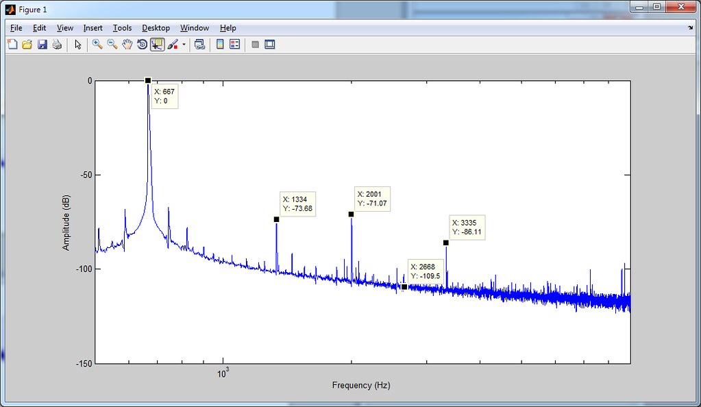
I remeasured (Xonar in loopback this time), did the mods above and measured again
Standard:

Mod:
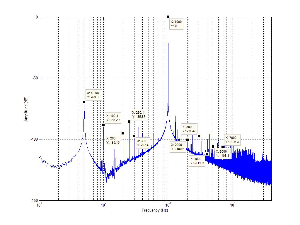
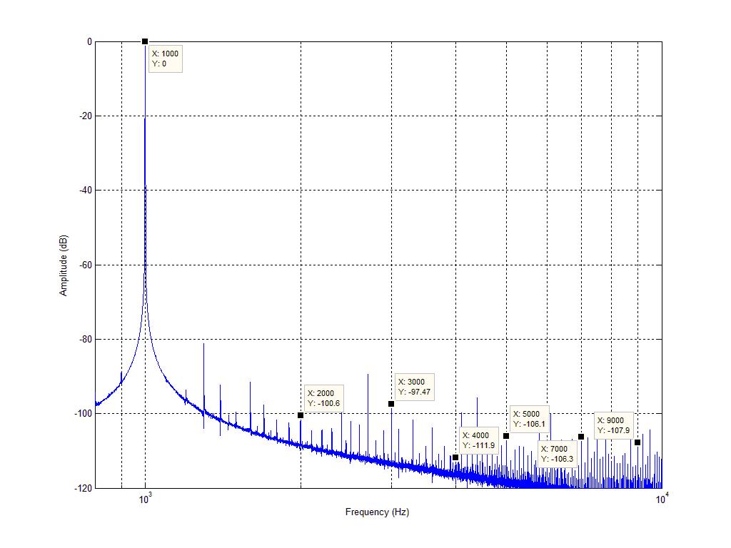
So distortion performance has gone from ~0.04% to ~0.0023% @ 1watt. gotta be happy with that One odd thing i noticed is that R222/R268 were connected to the INPUT side of L201/L202 contrary to the schematic. Not sure if that was intentional or a mistake on the PCB. Doesn't seem to affect performance.
I remeasured (Xonar in loopback this time), did the mods above and measured again
Standard:
Mod:
So distortion performance has gone from ~0.04% to ~0.0023% @ 1watt. gotta be happy with that
One odd thing i noticed is that R222/R268 were connected to the INPUT side of L201/L202 contrary to the schematic. Not sure if that was intentional or a mistake on the PCB. Doesn't seem to affect performance.
Last edited:
No worries Greg
I managed to get my hands on two more of these amps - they have a stylised font on the front panel silkscreening and the DSE logo is silkscreened instead of a badge.
The internal construction is the same - only a few capacitors differ in brand.
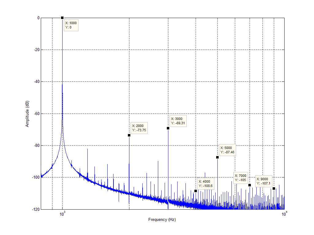
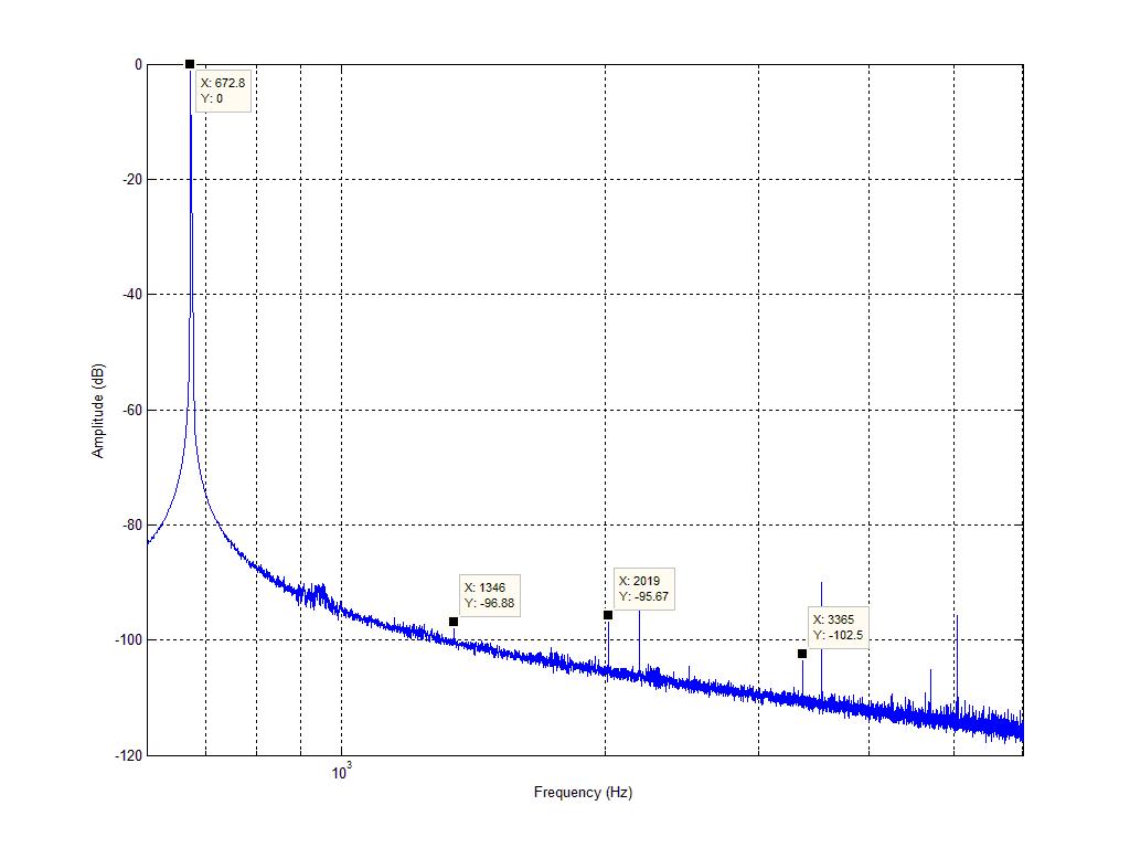
I thought it would be interesting to see what performance was like with the preamp still installed. Here is 1W @ 8ohm:
(ignore the THD measurement, it's wrong, correct result is 0.29% THD)
Looks like the transformer might be better on this amp, either that or my mains supply was cleaner during this test (haven't really looked into it). Distortion is significantly worse than my first amp, i measured R212/R262 and found 19mV on one channel and 10mV on the other. This equates to 68mA and 36mA bias currents - seems low. The above measurement happens to be from the channel biased at 36mA. Both of the 'new' amps also run very cool at idle accordingly - my first amp ran warm even before mods.
I managed to get my hands on two more of these amps - they have a stylised font on the front panel silkscreening and the DSE logo is silkscreened instead of a badge.
The internal construction is the same - only a few capacitors differ in brand.
I thought it would be interesting to see what performance was like with the preamp still installed. Here is 1W @ 8ohm:
(ignore the THD measurement, it's wrong
, correct result is 0.29% THD)Looks like the transformer might be better on this amp, either that or my mains supply was cleaner during this test (haven't really looked into it). Distortion is significantly worse than my first amp, i measured R212/R262 and found 19mV on one channel and 10mV on the other. This equates to 68mA and 36mA bias currents - seems low. The above measurement happens to be from the channel biased at 36mA. Both of the 'new' amps also run very cool at idle accordingly - my first amp ran warm even before mods.
Last edited:
- Status
- This old topic is closed. If you want to reopen this topic, contact a moderator using the "Report Post" button.
- Home
- Amplifiers
- Solid State
- DSE A2760 Amplifier (aka Koda-261)