Hi all,
I'm a new member to DIY, but a member in good standing at AK.
I have a pair of Adcom GFA-565s I recently aquired and after reading many strings I have determined my +7 to +50v dc offset is being caused by the leaky caps & contaminated driver board that anatech and other have talked about.
Sadly, I didn't check for DC before hooking my new amps to the low-end of my IRS Gammas, and I literally burned/smoked/melted my unobtanium woofers , but that is another part of the story. Shame on me for not checking first!
 I am working will the seller of the amps, and he's being a stand up guy and wants to help me get them repaired.
This is a callout for anatech. Could you email/pm me? As a new member I am not allowed to email yet. You can also get me with the same name at AK. Echowars (Glenn) on AK speaks very highly of you guys over here.
I see the leaking electrolyte. Is is possible to send you both of the driver boards for you to work your magic? I understand how difficult it is to do without having the amps, but shipping the monos to Canada is not in the cards.
I was hoping someone (anatech or another member that had experience/luck with removing the electrolyte) would be willing to replace Opamps, caps & zeners (shotgun) and clean like crazy. Maybe someone has a 565 that could be used as a verifying amp?
I have the skills to R&R the components, but with the sourcing & ordering parts, and correct cleaning procedures, I would prefer to have someone else do it, that has had success.
I apologize if I have crossed any forum etiquette by asking for a specific member contact. I think I'm ok, but hate newbies on my other forums that come in and expect things to be handed to them.
Thanks to all for any suggestions. I'm in MN, if there are any members in the area that want to give it a stab. I will drive the amps where I need. If someone were willing to put together a parts package for both boards, I would also be willing to buy it, and give it a shot myself.
I'm a new member to DIY, but a member in good standing at AK.
I have a pair of Adcom GFA-565s I recently aquired and after reading many strings I have determined my +7 to +50v dc offset is being caused by the leaky caps & contaminated driver board that anatech and other have talked about.
Sadly, I didn't check for DC before hooking my new amps to the low-end of my IRS Gammas, and I literally burned/smoked/melted my unobtanium woofers
, but that is another part of the story. Shame on me for not checking first! I am working will the seller of the amps, and he's being a stand up guy and wants to help me get them repaired.This is a callout for anatech. Could you email/pm me? As a new member I am not allowed to email yet. You can also get me with the same name at AK. Echowars (Glenn) on AK speaks very highly of you guys over here.
I see the leaking electrolyte. Is is possible to send you both of the driver boards for you to work your magic? I understand how difficult it is to do without having the amps, but shipping the monos to Canada is not in the cards.
I was hoping someone (anatech or another member that had experience/luck with removing the electrolyte) would be willing to replace Opamps, caps & zeners (shotgun) and clean like crazy. Maybe someone has a 565 that could be used as a verifying amp?
I have the skills to R&R the components, but with the sourcing & ordering parts, and correct cleaning procedures, I would prefer to have someone else do it, that has had success.
I apologize if I have crossed any forum etiquette by asking for a specific member contact. I think I'm ok, but hate newbies on my other forums that come in and expect things to be handed to them.
Thanks to all for any suggestions. I'm in MN, if there are any members in the area that want to give it a stab. I will drive the amps where I need. If someone were willing to put together a parts package for both boards, I would also be willing to buy it, and give it a shot myself.
Thanks for feeling my pain about the IRS woofers. My audio karma must be pretty good, as this is where I am at so far:
The control woofer ohms out at around 1.2 ohm. I need to pull the other control woofer, but I think the VC is ok. It just trashed the surround (I hope). I talked to Bill Watkins and he is willing to refoam it, and can leave the accelerometer & servo board in place because he doesn't remove the dust cap to refoam. Instead of shimming the VC to center it, he feeds a LF signal to it when he attaches the surround.
The other woofer is trashed. You couldn't rewind the VC if you wanted to. I was hoping the entire VC could be removed and a new one attached to the carbon cone. Every speaker guy I talked to says no. BUT (shhhh, don't tell ANYONE this) they are still available from Harmon Group. They look slightly different if I remember correctly (a friend with Betas ordered one), but are OEM part number & spec'd. I think the dust cover is a different color or something. I'm ordering one today.
Glenn, I didn't email you about the Adcom boards for two reasons; You are the busiest man in show business, and you recommended the DIY guys to someone else that questioned you on Adcom issues. If you have time sooner than later, and would be willing to try what I've listed about (having me send just the driver boards), lets talk (PM).
Hopefully I get some responses but I think I may end up tackling this myself, which I don't really want to do. I'm out the repair costs on the Gammas, and would rather have the seller of the amps take care of fixing them (although he only has $250 to help me fix them). I'm afraid since no one has taken up the offer to pull the components and ultrasonic clean the board, I'll be getting the toothbrush & Simple Green out. I can't afford to bring them to a local shop right now since the extra $250 won't go very far, and I still need to cover the other repairs as well. Hopefully the worlds most convoluted crossover is ok (you should see it), but I won't know that till I replace the drivers. I think the entire xover is bypassed on the LF, when in biamp mode using the servo.
I just can't believe I was so STUPID to hook used amps up to my perfectly good, working IRS system without doing a checkout first. I was already biamping with a Yamaha B-2x pushing the lows, and was really just experimenting to see if the Adcoms made any difference in damping. Lesson learned.
hot soapy water will safely remove the electrolyte, at least the water soluble portions of it, and alcohol will remove the oils. if any small caps exploded look for any bits of aluminum that might have wedged themselves between component leads. there may be pieces of the cover as well as pieces of the aluminum coiled plates fom the innards of the cap. if its just the big caps, replace the caps, and clean the board. the big caps usually vent without much collateral damage. if you know what caused the caps to fail, make sure its completely fixed. i'd be willing to look at the amp, but i'm in colorado.
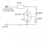
btw, for anybody who needs a "quick and dirty" method of checking for offset, here's a device i built from a few spare parts, and use on a daily basis. it indicates polarity and the brightness gives a rough estimate of voltage. it turns on at about 4V and i've tested up to 65V rails without burning it out yet. it lights up red for positive and blue for negative. if you're expecting higher rail voltages (like 100V), increase the resistor to 47k-75k. i got the LED from spares that come with Klipsch sub amps when i replace the amp module.
btw, for anybody who needs a "quick and dirty" method of checking for offset, here's a device i built from a few spare parts, and use on a daily basis. it indicates polarity and the brightness gives a rough estimate of voltage. it turns on at about 4V and i've tested up to 65V rails without burning it out yet. it lights up red for positive and blue for negative. if you're expecting higher rail voltages (like 100V), increase the resistor to 47k-75k. i got the LED from spares that come with Klipsch sub amps when i replace the amp module.
Attachments
Hi Numbdiver,
I'm really sorry to hear about your woofers. I guess this is a lesson learned for all time.
I always check for DC offset, even with a new amp. Some systems (Krell for one) will go DC if the preamp has DC offset too. Check always.
I can clean the boards for you, but the border sucks. If you can find someone in the USA, it might be easier.
I'll have to disagree with unclejed613 here (sorry). This electrolyte is tenacious stuff. Hot soapy water will not cut it. You need an ultrasonic cleaner and a water based degreaser. The stuff is not visible either, so it will look clean. It will probably take a few cycles through the ultrasonic cleaner.
First, dismount all the capacitors, the op amp and trimmer controls. Also remove any resistors or other components that were in the area where the fluid went. Check for corrosion on the leads. You will need to clean these parts separately, then use a toothbrush and clean more. The way you can tell if the board or parts are clean is to smell them. Heat the leads (or pads) up with a soldering iron. You will smell this stuff if it's there. Clean until you can't smell once the soldering iron heats the parts up.
The main trick is - clean until you are sure it's clean. Like cleaning a gun until the patch comes out clean.
I'm pretty sure you can do this. I use "Simple Green".
-Chris
I do not see many Adcom's, or maybe I might have gone shopping for an ultrasonic cleaner (but it might be nice for cleaning receiver knobs & stuff).
Shipping across the border is a little bit of a pain, but USPS and Canada Post is reasonably priced for a small board, and border fees ought to be small.
I am not hurt that you didn't contact me. About all I could offer for months in the future would be words of solace. Things are busy around here indeed.
anatech, you reminded me of a way to neutralize corrosive salts.......
some rifle ammo contains corrosive salts, and the way to neutralize it is to spray ammonia inside the barrel. i used to keep a bottle of ammonia (without any addtives like scents or colorants) in my shooting bag. soaking the inside of the barrel and then running an ammonia soaked patch through it would neutralize the corrosive salts and make it easier to clean later.
some electrolytic caps have electrolytes made with fish oil, which is what gives their electrolyte the characteristic smell of burnt fish when they smoke, and that's why i suggested alcohol as part of the cleaning. the hot soapy water thing actually was a process used at a shop i worked at before ultrasonic cleaning was invented. the board was cleaned in a bath of hot soapy water, then rinsed in a bath of hot water, then dried under hot forced air. this was in a city on the east coast where the "creeping green crud" was a common occurrence just from the salt and moisture in the air.
I very much appreciate all the tips everyone is giving me.
It looks like I may decide to tackle this on my own. I do have an aqauintence that works in a very high tech environment. In fact, he designs caps (Phd) for a living. He should be able to remove the stuff. He said they would use de-ionized hot ultrasonic with no detergents.
Multiple baths? How long as to not destroy the board integrety? He has the correct drying oven, so it won't get wrecked in there. he hasn't done a wet bath to a board before so any other tips would be great.
Also, since I'm limited on equipment (& skills), I will be shotgunning parts. I was planning on replacing OpAmps, caps (to high-temp Panny), and zeners. Anything else I should order at the same time? I'll probably order everything over the 'net from Newark as they probably have everything.
Lastly, someone talked on one of the forums about a couple of resistors that keep the input ground floating above chassis ground. And these can also cause offset issuses if they open. Where are they? If it is as simple as checking resistance between input ground and the ground pin on the plug, one amp reads about 110ohms, and one shows to be open (infinite).
Thanks once again for all the help! Once these are back together, I would still like to be hand-held through the biasing/offset adjustments if that is ok. I will try and purchase a schematic from Adcom as well.
Have a great day!
Hi unclejed613,
My my, that is some old ammo! Are the primers still good? Hangfire heaven, here we come! All my stuff is from the late 80's. Hmm, they're getting on in years too. Mostly 7.62 with some .303 Brit mixed in.
Hey Glenn!,
You really ought to pick one of these up. Ultrasonic cleaners are magic on knobs, screws and other small parts. I wish I had a bigger one as well. My wife and three daughters have clean jewelery, so they can't complain. Anita even has a mini one for her contacts. Guess she liked the idea.")
Hi Numbdiver,
Try not to over think this. You have a abnormal mess on your hands. Normal PCB cleaning is ineffective. You are capable of doing this if you can get access to an ultrasonic cleaner and some non-flammable degreaser. Your friend is well meaning, but he was taught the proper accepted way of cleaning a PCB. So was I and this is not very effective here.
-Chris
Edit: Really bad spelling
Yes! and Yes again!some rifle ammo contains corrosive salts, and the way to neutralize it is to spray ammonia inside the barrel.
My my, that is some old ammo! Are the primers still good? Hangfire heaven, here we come! All my stuff is from the late 80's. Hmm, they're getting on in years too. Mostly 7.62 with some .303 Brit mixed in.
Hey Glenn!,
You really ought to pick one of these up. Ultrasonic cleaners are magic on knobs, screws and other small parts. I wish I had a bigger one as well. My wife and three daughters have clean jewelery, so they can't complain. Anita even has a mini one for her contacts. Guess she liked the idea.
Hi Numbdiver,
Too high tech. This electrolyte was a defective batch that every industry suffered from. This approach is too nice and may not get the job done. Understand that this stuff gets into the PCB material itself, under the solder mask too. You need more aggressive cleaning solutions here. Cleaning as per MIL-whatever, or Hewlitt-Packard methods are not intended for this situation.He said they would use de-ionized hot ultrasonic with no detergents.
Not at all. These are epoxy boards. The time in the cleaner will probably be a couple 5 minute sessions, or more. The PCB will be fine. Any electrolytic caps will not (doesn't matter, remove them), trimmer controls will not like this either, remove and label first.Multiple baths? How long as to not destroy the board integrety?
First, rinse with clean water, the final rinse can be pure H2O. Shake the excess water off first, and follow that with a hair dryer set to low heat. Keep moving the dryer around and angle across the PCB to blow any other water out from small spaces. Finish up by air drying a day, you will be fine. I normally test for electrolyte after the second clean cycle and continue after each until the stuff is gone.He has the correct drying oven, so it won't get wrecked in there.
Okay, fine. Then take some pictures first with a digital camera. Then, depopulate the PCB. Keep the op amp and the TO-92 zeners, clean them by hand. If the leads are rotten, you can replace those parts. Be aware that those are specifically selected types. You can not replace them with normal zener diodes or a normal range op amp. Hint: the current draw on that op amp is very low. So is the DC offset and it need not be a fast one.Also, since I'm limited on equipment (& skills), I will be shotgunning parts
The 10 (or 100) ohm resistors break a possible ground loop. They can be burned out. Just test them, replace if you want.Lastly, someone talked on one of the forums about a couple of resistors that keep the input ground floating above chassis ground.
If memory serves, you will read 200 ohms between the RCA grounds and 100 ohms to chassis ground from each. It is that simple.If it is as simple as checking resistance between input ground and the ground pin on the plug, one amp reads about 110ohms, and one shows to be open (infinite).
If you buy the entire service manual (recommended), the entire procedure will be laid out for you. Setting the bias takes some time and you will need an oscillator (source of a tone about 1 KHz) and a pair of dummy loads close to 8 ohms. You may be able to buy 225 watt, 7.5 ohm power resistors with a pair of clamps. My 250 watt, 8 ohm Dale resistors cost me $50 each about 20 years ago. Add to that the large heat sinks they needed and the milling to make the other side flat. Get the tubular 7.5 ohm resistors, they are close enough.I will try and purchase a schematic from Adcom as well.
Try not to over think this. You have a abnormal mess on your hands. Normal PCB cleaning is ineffective. You are capable of doing this if you can get access to an ultrasonic cleaner and some non-flammable degreaser. Your friend is well meaning, but he was taught the proper accepted way of cleaning a PCB. So was I and this is not very effective here.
-Chris
Edit: Really bad spelling
Ok Chris,
Thanks for the tips. Since I can't really do anything about the solution in the ultrasonic cleaner (they are in the medical industry and I'm not going to ask him to change their standard cleaner), I will tootbrush/simple green/rinse/repeat before giving them to him for the final multiple ionized water baths.
The OpAmps are corroded. I was planning on using: http://www.newark.com/59K8973/semic...rcuits/product.us0?sku=analog-devices-op97epz which is an Analog Devices OP97EPZ. I think that was mentioned (if not by manufacturer) in another post.
The zeners would be:
http://www.newark.com/26K3669/semic...sku=on-semiconductor-mbd301g&_requestid=63307
I think they are small signal diodes that are recommended.
Do these look ok to you? I apologize to any vendors that may use this forum. I only choose Newark, as they are who I know I can e-order from.
Last question; physically where are the ground look resistors we have talked about?
Once again, I thank you for sharing your knowledge and skills in this matter.
so this was a specific cap formulation we're talking about here..... i wouldn't be in the audio business if there was nothing left to learn....
OT, but only for a second... anatech, it was 7.62x54R russian surplus ammo (1943 vintage) and some 8mm 1944 headstamped german ammo (both of them WWII surplus) which i bought for a couple of WWII surplus rifles i have.
ok, back on topic. it seems there were a lot of mistakes made over the years both with cap formulations and cap construction, even by the most reputable manufacturers. Sprague made a line of caps, that to this day i see the same failure on over and over. they're the Atom caps with the red epoxy seal, and both in the radial and axial types. the connection between the positive lead and the positive plate burns open right below the epoxy, leaving a black dot next to or a black circle around the positive lead. these caps usually also have a clear heat shrink sleeve around them. it also doesn't seem to matter whether it's wire leads or screw terminals, they still fail. i once saw a very expensive lab standard digital volt meter that had 20 of these in parallel in the power supply, and 18 of them had failed. i've seen other equipment with them in them (including audio amps). and i replace them as soon as i see them now. so i find it not at all unusual to hear that there were caps out there with a bad formulation, maybe even in production for years.
Hi Numbdiver,
Those diodes are incorrect. I don't recall the exact op amp replacement, but somewhere there are a few references to them. I think Walt Jung commented on this.
The diodes you need will look like a transistor with two legs. They are a low noise 7 V breakdown device. You will probably see those numbers near where the op amp is mentioned.
Hi unclejed613,
There are stories on this. The most popular is a factory that got a partial formula. They went on to sell it to many capacitor plants. Nasty stuff.
-Chris
Those diodes are incorrect. I don't recall the exact op amp replacement, but somewhere there are a few references to them. I think Walt Jung commented on this.
The diodes you need will look like a transistor with two legs. They are a low noise 7 V breakdown device. You will probably see those numbers near where the op amp is mentioned.
Hi unclejed613,
Are you going to try and fire them? Erk! You may be further ahead using the brass and reloading them with modern components. That is time consuming to work up to the right load. Be careful with that old stuff. I know what having a hang fire feels like. With rounds that size you stand a chance of flying brass, unlike a .22 round (not to say they aren't dangerous).it was 7.62x54R russian surplus ammo (1943 vintage) and some 8mm 1944 headstamped german ammo (both of them WWII surplus) which i bought for a couple of WWII surplus rifles i have.
There are stories on this. The most popular is a factory that got a partial formula. They went on to sell it to many capacitor plants. Nasty stuff.
-Chris
anatech said:Hi Numbdiver,
Those diodes are incorrect. I don't recall the exact op amp replacement, but somewhere there are a few references to them. I think Walt Jung commented on this.
The diodes you need will look like a transistor with two legs. They are a low noise 7 V breakdown device. You will probably see those numbers near where the op amp is mentioned.
Hi unclejed613,
Are you going to try and fire them? Erk! You may be further ahead using the brass and reloading them with modern components. That is time consuming to work up to the right load. Be careful with that old stuff. I know what having a hang fire feels like. With rounds that size you stand a chance of flying brass, unlike a .22 round (not to say they aren't dangerous).
There are stories on this. The most popular is a factory that got a partial formula. They went on to sell it to many capacitor plants. Nasty stuff.
-Chris
oops, took too long to edit.......
if you want we can branch the vintage rifles to the "Everything Else" forum, as that's one of my hobbies. i like studying the innovations, technical quirks, and history in military small arms....
the zeners should be replaced with the proper type. most zeners are very noisy, which is why i'm surprised any manufacturers use them in audio amps these days. i've even seen a new 2007 model (made by American Audio) using zeners for the op amp and diff amp supplies in their amps. why? a couple of cents difference between 78xx and 79xx chips and a couple of 5 watt zeners and 2 huge 20 watt resistors? if it's oddball voltages, there's still no reason. there are 78xx and 79xx chips in single volt increments up to 15V, and even if there weren't, there is an app note from NSC that says you can put forward biased diodes between the ground pin and ground to fudge the voltage. LM317 type regulators are almost as simple to use, but have even more flexibility for voltage settings. the American Audio amp mentioned above also had a quirky way of muting the amp modules if the protection circuit tripped, a set of relay contacts would short the zener controlled rails to ground, shutting off the op amps and the diff amp.
as to cap formulations, i've seen equipment made from about 1920 to the present, and some cap manufacturers have tried some often bizarre formulations, and leave me asking "what were you guys thinking?????". one particularly nasty formulation broke down into raw ammonia (this was in a 1950's vintage TV set that i tried working on when i was about 12) after many years of sitting dormant in my grandfather's basement. boy did that clear out my grandfather's living room......
Hi Glenn,
Without looking, I can't be sure of that. My gut tells me they are singles in that Adcom.
Hi unclejed613,
Some zeners are not that noisy, especially the ones used in this Adcom. Another device that can be used are the adjustable shunt regulators.
The 78xx and 79xx have poor noise rejection at the higher frequencies. I haven't used those in audio circuits for at least 10 years and probably longer. The LM317 and LM337 chips are supposed to be better for noise. They can easily be set for any odd voltage. A nifty shut down can be made by shorting the lower voltage set resistor to ground. This drops your output voltages to about 1.2 VDC. Pretty neat eh? Revox was fond of doing this.
I tend to make my own regulators using a CCS and zener, or shunt regulator. You can improve the high frequency performance that way. You can also use an RC filter on the output of your regulator for low level stages as the change in current draw isn't much.
Back to this amplifier. Use the original high quality, low noise shunt regulators, or a direct sub. If you can clean up the old parts, go ahead and use them.
-Chris
i just recently read an article that shed an interesting light on why 3 terminal regulators behave badly at high frequencies and what to do about it. the article was by Bob Pease (the senior analog engineer at NSC) and he described the operation of 3 terminal regulators as "active inductors" meaning that if you just indescriminately place caps at the inputs and outputs, you get a resonant circuit (with gain, maybe even enough to oscillate). i plan on reading the article in depth this week, but the idea that regulators act like an inductor actually would explain why one person might have them work fine most of the time, and another person might have them misbehave most of the time. it's all in the application and external components that one would prefer. i've seen many instances where somebody sees 10uf caps used at the input and output in a circuit, and it works well for whatever application (i've done this myself too...) and says "oh, 10uf caps work well here, so i'll use 10uf caps too...", and get in the habit of almost always using 10uf caps with 3 terminal regulators. eventually, doing this will come back to bite you, since chances are pretty good that eventually you may happen on an application where this is simply THE wrong application of this particular combination of components. Bob Pease designed 3 terminal regulators, so i think he's not only had a lot of experience with them, but has had to field a lot of questions about them over the years. there are also different processes for making 3 terminal regulators, so an NSC LM7812 might work well in a circuit, but a KIA or a hitachi (does hitachi even make them anymore?) might oscillate. there are also direct replacements for the original 78xx and 79xx devices with improvements (such as also being a Low Dropout Regulator or having the reverse bias bypass diode built in), and so might behave a lot better than the originals.
the article also shows ways of testing their high frequency behavior that could probably be a big help in designing circuits that don't misbehave at high frequencies.
another approach would to use discrete transistor regulators, using fast enough devices to maintain good regulating and filtering action well above the frequency limits of most 3 terminal regulators. i don't really like using resistor-zener regulators because they tend to be high rate-of-failure circuits, and actually have a relatively high output impedance. noise is easily bypassed with a capacitor, so unless the zener is getting ready to fail, or the cap dries out, it's usually not very noisy. there's also a simple (1 transistor, 1 or 2 resistors, and one cap) circuit that acts as a capacitance multiplier on power supply rails, and so can filter a power supply rail extremely well without huge caps.
The original Adcom 2A op-amp part is made by Linear Technologies LT1012, however Walt Jung recommended an Analog Devices OP97 IC, which has worked flawlessly in the 3 565 rebuilds I've done.
You'll need Analog Devices part # OP97FPZ in the 8-pin DIP package.
And please don't get me started on firearms and ammunition, I could drone on for days.
You'll need Analog Devices part # OP97FPZ in the 8-pin DIP package.
And please don't get me started on firearms and ammunition, I could drone on for days.
Well, I've decided to give it a try. They certainly could of made it easier for me to get the board out though! I labeled everything, and decided for safety's sake, I'm doing one at a time, so I have a reference, just in case. Caps were absolutely leaking. Not a lot of corrosion elsewhere, which is a good sign.
I emailed Adcom about a manual, but haven't gotten a response. I'll try calling, but does anyone have a scan if I can't get one?
MjrAudio: Thanks for verifying the correct AD op amp number!
You guys went off on a diode tangent that while interesting reading, kind of got away from anatech's statement that I was looking at the wrong type. He mentioned a transistor-looking style with 2 legs. I do see some Adcom J2/8934M 3-legged thingys that have a diode symbol printed on the board. Are those them?
Lastly I still need the physical location of the these resistors so I can test them:
"The 10 (or 100) ohm resistors break a possible ground loop. They can be burned out. Just test them, replace if you want."
Sorry for all the questions. I want to do this right, and until I can find a service manual, you guys are my only source of info.
Thanks once again!
- Status
- This old topic is closed. If you want to reopen this topic, contact a moderator using the "Report Post" button.
- Home
- Amplifiers
- Solid State
- Adcom GFA-565 Driver Board Cancer