Hi All
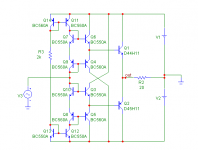
I was wanting to build a discrete buffer for a preamp/headphone amp, so I started with a classic diamond buffer design and I found that I had to increase the bias to drive the low impedance loads at low distortion, but then the output devices would get hot because of the heavy bias.
I needed a design that can supply large current to the output devices when the output devices needed it.
So I came up with this design here.
Enjoy
Tim
Attachments
Improving upon the Improved Diamond Buffer
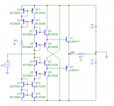
The previous iteration of the design was very good, but its input impedance was about 7k which is fine if the circuit is to be used as a buffer to a opamp but not so good if it will be used by itself.
The changes have increased the input impedance to about 150k but reduced the voltage swing by +- 1V and have lowered the distortion in to 32R slightly from about 0.003% to 0.002%
Otherwise the rest of the specs are the same with 0.12R output impedance, theoretically 470MHz 3dB bandwidth and vanishingly low distortion into 100R
Cheers
Tim
Attachments
I was wondering when somebody would ask me that.
According to the unreal world that is Microcap 6, I don't need them because I can't get the distortion any better than it is and if I add them to my simulation the distortion gets worse.
But you are right, in a real world my parts won't be so well matched and I will need some degeneration.
I will be having a go at the prototype soon so we shall see.
TzeYang said:no degenerative resistors for the drivers and the mirrors?
TimS said:But you are right, in a real world my parts won't be so well matched and I will need some degeneration.
Alternatively:
http://au.farnell.com/1354180/semiconductors-discretes/product.us0?sku=that-corporation-that340p14-u
It isn't simply a distortion matter: without resistors, it will go into thermal runaway at an incredible speed.TimS said:I was wondering when somebody would ask me that.
According to the unreal world that is Microcap 6, I don't need them because I can't get the distortion any better than it is and if I add them to my simulation the distortion gets worse.
I suggest you power your prototype with a good, current limited lab PSU. Otherwise the experiment may end in heath and smoke...
Circuit looks very cool to be honest (though with emitter resistors it'll be even better).
There's one thing I don't understand, which of the following is of higher Zi (input impedance):
1) Source sees two diodes.
2) Source sees the bases of the driver transistors (typical diamond buffer structure).
There's one thing I don't understand, which of the following is of higher Zi (input impedance):
1) Source sees two diodes.
2) Source sees the bases of the driver transistors (typical diamond buffer structure).
... but you have a real world also with not equal parts at different temperatures.TimS said:I was wondering when somebody would ask me that.
According to the unreal world that is Microcap 6, I don't need them ..

Your statement is interesting. Here is where the experience comes in

OK
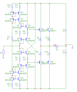
This version I have included the degeneration resistors and the BC847B's are intended to be BC847BV dual transistor pairs to improved temperature tracking, possibly matching as well as reducing parts count.
Doubled the output devices to reduce the output impedance,
The THAT 300 devices look very nice, if they were not so expensive I would probably give them a try.
Cheers
Tim
Attachments
peranders said:
... but you have a real world also with not equal parts at different temperatures.
Your statement is interesting. Here is where the experience comes in
Other peoples experience is what I am here for.
")
TzeYang said:Circuit looks very cool to be honest (though with emitter resistors it'll be even better).
There's one thing I don't understand, which of the following is of higher Zi (input impedance):
1) Source sees two diodes.
2) Source sees the bases of the driver transistors (typical diamond buffer structure).
Though it is not obvious the 2 diodes are in series with the high impedance of the current sources.
The high impedance dominates the 2 components.
Cheers
Tim
Hi Tim,
Those are $7.78 each in singles from Newark in Canada.
Probably well worth it considering the thermal matching and reduction this means from hand matching. Never mind over buying what you need to find matched transistors. This I know from experience.
A link I don't know if this will work.
-Chris
Those are $7.78 each in singles from Newark in Canada.
Probably well worth it considering the thermal matching and reduction this means from hand matching. Never mind over buying what you need to find matched transistors. This I know from experience.
A link I don't know if this will work.
-Chris
anatech said:Hi Tim,
Those are $7.78 each in singles from Newark in Canada.
Probably well worth it considering the thermal matching and reduction this means from hand matching. Never mind over buying what you need to find matched transistors. This I know from experience.
A link I don't know if this will work.
-Chris
Thanks Chris
But once you do the conversion to NZ dollars it starts to look expensive to me.
But you are right if i could get close to implementing my original designs their simulation looks like the proverbial wire with current gain and no global feedback.
Cheers
Tim
Hi Tim,
I'm the same way. I hate to part with a buck. It takes a while (years) to figure out that the more expensive part can both save money and increase performance.
I don't know if that holds in this case. Another option is available. Surface mount packages exist with matched NPN and PNP parts. That would give you a great front end. I haven't look those up yet, but I do know they exist. Cyrus uses them for example. I expect they should be less money.
-Chris
Hi
I can vouch for those THAT arrays. I have used the 340 matched complementary and plan to use them in my next project (SOIC 14). I just spent $50 for 8 of them though. By far the most expensive part in the circuit but on a good note, you will need little or no degeneration with them if you use them for current mirrors. You get what you pay for. I'm using them for the amplifying transistors in my circuit since there are no mirrors in it.
I can vouch for those THAT arrays. I have used the 340 matched complementary and plan to use them in my next project (SOIC 14). I just spent $50 for 8 of them though.
By far the most expensive part in the circuit but on a good note, you will need little or no degeneration with them if you use them for current mirrors. You get what you pay for. I'm using them for the amplifying transistors in my circuit since there are no mirrors in it.anatech said:Hi Tim,
I'm the same way. I hate to part with a buck. It takes a while (years) to figure out that the more expensive part can both save money and increase performance.
I don't know if that holds in this case. Another option is available. Surface mount packages exist with matched NPN and PNP parts. That would give you a great front end. I haven't look those up yet, but I do know they exist. Cyrus uses them for example. I expect they should be less money.
-Chris
CBS240 said:Hi
I can vouch for those THAT arrays. I have used the 340 matched complementary and plan to use them in my next project (SOIC 14). I just spent $50 for 8 of them though.
Well you guys are convincing me.
So a question for you, how would you split the THAT arrays up?
Eg would you use a whole THAT 320 for the top current mirror and a THAT 300 for the bottom or would you split 2 THAT 340 arrays between the top and bottom current mirrors? Or would you do something else.
The first idea would give me an easier layout but the second idea would mean the upper and lower current mirrors would be closer matched.
And for the input section my first thought would be to have a THAT 340 on the top and the bottom, but then maybe splitting the arrays would give a better match.
What do you guys think?
Cheers
Tim
Hi Tim,
Without having read the data sheet, I'll offer you some general ideas.
Keep in mind what sections of your schematic that should be in thermal contact. Think of which parts should not be in thermal contact.
Watch your maximum voltage between pins or sections. This is probably high since they are using oxide isolation in wells, but don't count on this.
If you consider the above points, a solution will suggest itself.
Hi CBS240,
I don't have any yet, but they are on my mind. I'm glad to hear they work out for you. These are also supposed to be very quiet, low noise.
-Chris
Hi Tim
In the datasheet it states the matching is between devices of like polarity. So the 340 has 2 matched NPN and 2 matched PNP transistors. The NPN is not exactly matched to the PNP, but I don't see how that will effect your circuit. IMO, I like swap mirrors better than cascade mirrors. But you’re paying a lot more to have separate matched dies in one package. (That is the big advantage with these in that they are not monolithic.) Is it really necessary to have a compound mirror? for THAT price.....
IME, you want to use these at around 1 or 2mA, they perform nicely. They are fast and very low noise, at least in my circuit. I measure a current gain of about 85, which is close to the datasheet, but much less than the Hfe of a BC550. I don't think this is a big drawback considering all the other positive properties of these transistor arrays. A few more uA of base current? Big deal.
For best noise results don't leave the substrate floating.
I have also used D44 and D45. These are nice linear TO-220 BJT’s up to about 4-5A. Fast with plenty of gain. But are they really needed to drive 32 Ohms at +/-15V? Or are these not the devices you are referencing?
Anyway good luck
My
In the datasheet it states the matching is between devices of like polarity. So the 340 has 2 matched NPN and 2 matched PNP transistors. The NPN is not exactly matched to the PNP, but I don't see how that will effect your circuit. IMO, I like swap mirrors better than cascade mirrors. But you’re paying a lot more to have separate matched dies in one package. (That is the big advantage with these in that they are not monolithic.) Is it really necessary to have a compound mirror? for THAT price.....
IME, you want to use these at around 1 or 2mA, they perform nicely. They are fast and very low noise, at least in my circuit.
I measure a current gain of about 85, which is close to the datasheet, but much less than the Hfe of a BC550. I don't think this is a big drawback considering all the other positive properties of these transistor arrays. A few more uA of base current? Big deal. For best noise results don't leave the substrate floating.
I have also used D44 and D45. These are nice linear TO-220 BJT’s up to about 4-5A. Fast with plenty of gain. But are they really needed to drive 32 Ohms at +/-15V? Or are these not the devices you are referencing?
Anyway good luck
My
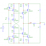
Hi Aurelian
Funny enough I have already done such a circuit and it works great.
I think the others who were on this topic would approve too because it has everything they were suggesting too and it achieves the distortion, bandwidth and load driving performance that I was after.
Funny enough I have already done such a circuit and it works great.
I think the others who were on this topic would approve too because it has everything they were suggesting too and it achieves the distortion, bandwidth and load driving performance that I was after.
Attachments
- Home
- Amplifiers
- Solid State
- Improved Diamond Buffer Design