I think Tim is basically right: this circuit has little to do with a conventionnal CFP anyway, and the D44/45 must have a pretty bad Hfe constancy over current, which explains the degraded linearity without buffer stage.Lumba Ogir said:TimS,
evidently, you only have a vague idea of how the CFP works, also, don't get fooled by those simulated distortion figures.
Additionnaly, the intermediate stage avoids the Miller effect caused by the Ccb of the output devices.
Why not. Both approaches have their own merit, but some thinking would be required to assess which is "best " (supposing there is such a thing)Lumba Ogir said:Elvee,
the D44/45 is a bad choice, I would endeavor towards these values.
Hi Tim,
Well, I like the new one you were sent, also Lumba's will work. Why not breadboard them both (you can reuse the bulk of the circuit)? I would definitely go with LED based CCS circuits.
Once you build them, you get a true measure of the performance and other undocumented "features".") Things like current draw and heat dissipation become real once you have one working in front of you. You also get to listen to them.
Things like current draw and heat dissipation become real once you have one working in front of you. You also get to listen to them.
You can replace the D44 and D45 with more suitable parts. The Japanese devices are better on average. Also look into using MJE1503x TO-220 devices. The part is not so critical that the circuit will work or not. The distortion and sound may depend on different devices.
Your original THD into 32 ohms was due to loading on Q19 and Q20, now you know why the Mosfets had lower THD. Buffering these parts was the answer you needed. That's why I used an EF type output stage.
-Chris
Well, I like the new one you were sent, also Lumba's will work. Why not breadboard them both (you can reuse the bulk of the circuit)? I would definitely go with LED based CCS circuits.
Once you build them, you get a true measure of the performance and other undocumented "features".
Things like current draw and heat dissipation become real once you have one working in front of you. You also get to listen to them.You can replace the D44 and D45 with more suitable parts. The Japanese devices are better on average. Also look into using MJE1503x TO-220 devices. The part is not so critical that the circuit will work or not. The distortion and sound may depend on different devices.
Your original THD into 32 ohms was due to loading on Q19 and Q20, now you know why the Mosfets had lower THD. Buffering these parts was the answer you needed. That's why I used an EF type output stage.
-Chris
Hi Chris
I like Lumba's circuit too, it uses less components, and still achieves almost as low distortion in to 32R, which appeals to me. (My version of Lumba's circuit is attached)
So yeah I think i will build a version of each.
I know the D44 and D45 are not ideal, but I have a lot of them so I will probably use them in my prototypes. I am planning to get the MJE1503X's for another project so maybe I will get a few more and try them as well.
Japanese transistors are as rare as hens teeth all the way down here so I usually do the best I can with what I can find.
You will have to post your design so we can have a look.
Attachments
Tim,
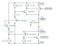
it looks nice now. The CFP needs to be biased in class A to avoid nasty cross-conduction and crossover distortion. The output impedance is very low, in practice set by R6/9. R16/17 is not necessary, the CFP provides for DC stability.
The collector output capacitance of 2SC5171/2SA1930 is 16/26pF versus 220/400pF for D45H11/D44H11. You have to build the circuit as there is a risk of oscillation, Q21/22 would worsen that considerably, fortunately, they are not required for anything.
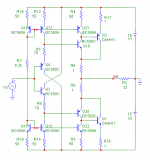
Here is my latest change.
Replacing the collector resistors with a constant current lowers the distortion into 32R to be as good as any previous circuit.
I am not sure why using BC560A and BC550A as current mirrors, compared to the BC560C and BC550C's, gives lower distortion in this circuit. But they do.
Maybe somebody can offer an explaination
Cheers
Tim
Attachments
Hi Tim,
I'll post mine once I'm happy with it. There is nothing special at all about it though. No flashes of insight, no brilliant circuit configurations. They just work really nicely, so I use them.
I use 2SA970 and 2SC2240 mostly, also 2SC3421 or 2SC3423 and 2SA1358 or 2SA1360 for signal stages. These parts are all fast and pretty linear. They are always thermally coupled together.
-Chris
I always use a CCS. It matters. There are times when you may need to cascode them as well.Replacing the collector resistors with a constant current lowers the distortion into 32R to be as good as any previous circuit.
Could be capacitance, beta or just the model. Even gain drop off with increasing current might be your answer. I have never simulated anything, so I'm throwing out guesses.I am not sure why using BC560A and BC550A as current mirrors, compared to the BC560C and BC550C's, gives lower distortion in this circuit.
I'll post mine once I'm happy with it. There is nothing special at all about it though. No flashes of insight, no brilliant circuit configurations. They just work really nicely, so I use them.
I use 2SA970 and 2SC2240 mostly, also 2SC3421 or 2SC3423 and 2SA1358 or 2SA1360 for signal stages. These parts are all fast and pretty linear. They are always thermally coupled together.
-Chris
Hallo TimS,
Have you made the prototype (with Cfp output stage) and can You tell us how this work? (measured distortion at various levels, frequecies and loads,slew rate, noise,thermal stability,offset,sound....)
You last version is with D44/45H11 or have you try other devices?
Thank You and Best Regards
semola
Tim,
You started off with a classic Diamond topology, which has one very strong point: zero NFB.
You now have added a CFP output stage, whichhas a huge amount of NFB, and will sound very different.
I believe you need to get soldering and LISTENING, simulations tell you zip about the real world.
Regards, Allen
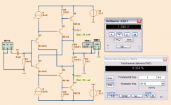
Diamond with Sziklai CFB output
shows low distortion as long as the bias is in Class A.
There is however possible to finetune
and get rather low distortion in Class AB.
Below a diamond sziklai follower for Headphone Amplifier
in Class A with only 0.004% THD
shows low distortion as long as the bias is in Class A.
There is however possible to finetune
and get rather low distortion in Class AB.
Below a diamond sziklai follower for Headphone Amplifier
in Class A with only 0.004% THD
Attachments
Diamond with Sziklai CFB output
shows low distortion as long as the bias is in Class A.
There is however possible to finetune
and get rather low distortion in Class AB.
Below a diamond sziklai follower for Headphone Amplifier
in Class A with only 0.004% THD
How does this work? I see zero volts C-E on the input transistors? Just wondering ... (Still a nifty circuit)
This is a buffer, Tim, unity voltage gain, NOT an amp, so you will need an additional stage or two out front. A tube would do nicely......
Hugh
There is still current gain and the output power is greater than the input power so I would of the superset amplifier but it is also of the sub set buffer.
How does this work? I see zero volts C-E on the input transistors?
RE lineups's szilaki buffer - I'm mistaken - there is voltage across the input transistors. I get it now.
OK
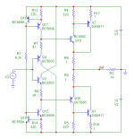
This version I have included the degeneration resistors and the BC847B's are intended to be BC847BV dual transistor pairs to improved temperature tracking, possibly matching as well as reducing parts count.
Doubled the output devices to reduce the output impedance,
The THAT 300 devices look very nice, if they were not so expensive I would probably give them a try.
Cheers
Tim
I built this one using bcv61 62 (monolithic current mirrors) and its by far the best buffer circuit i have EVER built. Comparing it to a classic diamond buffer and the ones with current mirrors Tim's circuit is even more transparent and stronger sounding. It truly sounds like nothing at all yet you still get the benefit of impedance matching so the music sounds fuller. Very nice.
Im wondering if the circuits that were posted here subsequently are better in every aspect (then i shall build them) or if the one i built was also as good as it gets. I feel like the pssr will be the best with the one ive built vs others. Not that i can understand these circuits completely
- Home
- Amplifiers
- Solid State
- Improved Diamond Buffer Design