Homemoder, Jam
The JLH buffer looks looks remarkable like a unity gain F5 with bipolar output stage.
I think there are several advantages to have a dual/split feedback:
- If the output clips at one of the rails, a single feedback amplifier would lose control of its feedback loop and it may oscillate or latch-up. Whereas if there is a second feedback loop, different voltage than the first, It would still be in control and your amplifier will be perfectly stable while clipping.
- If it is a symetrical complemetary design, like the F5 and the JLH, it can help to balance the 2 halves. ie instead of having 2 high gain stages (that are a complementary mirror to each other) in parallel, you put a feedback loop around each gain stage and then put them in parallel. You can even tweak the feedback of each half to ensure matching.
Jam,
Thanks for the feedback on my layout, I was hoping to keep cost down and just make it a 2 layer design and keep the ground plane on the top layer, but it looks like that is not possible.
Also, I like the FET/bipolar designs I will be giving them a closer look.
I am planning use my design to replace a pre-amp and I am thinking I will need another stage before the volume control so the FET/bipolar circuits may be a candidate.
Cheers
Tim
Thanks Tim, your analasys might be correct, I never really looked that closely at the circuit. Its good to have input from others I never thought of looking at it that way. Jam also locked on to this quickly. Maybe spice can reveal something on the clipping performance compared to the other circuit. JLH didnt mention anything about this but then again reading his stuff one has to do a lot of maths to discover why he designed certain circuits the way he did. Yes the resemblance to F5 is remarkable.
As an output buffer for low impedance headphones I think I would also go with a diamond buffer, I havent tried the fet one, cant get japanese p channels here and the n parts are just as difficult.
Nelson its a difficult decision to make, sometimes I prefer one, other times the other. Using the fet bjt cfp in a ltp could have interesting results I agree. Another good sounding combination is bjt mosfet cfp, but Ive only tried it in outputstages.
Jam I think you sent me an email, sorry I have not responded yet, as I havent had access to my account for some days. I recieve some sensitive business related mail through this account after changing from others but someone has again been able to locate this public address of mine and gain access into it. I have the authoristies looking into this again so I cannot respond for the time being.
 ).
).homemodder,
Sorry, Iwas under the impression that JLH used a single feedback path. It should sound very good as you say.
I wonder how it would compare to the jfet diamond buffer (non-feedback). This might be a good comparison between feedback and non-feedback circuits (I should say non-loop feedback before I get into trouble with the definition of feedback).
Regards,
Jam
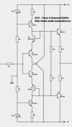
Below I have attach ACD (from Denmark )
version of his Diamond Buffer.
It is used within op-amp loop, to provide a Class A current output.
As can be seen, he uses the drop of one 2SC2240 and one 2SA970
to set the voltage across the output emitter Resistors.
And so bias into true Class A.
He also sells his PCB (without components) for a fair price.
I judge this as a very good circuit when we need a powerful line level buffer with hi-Fi quality.
http://audio-innovation.eu/shop/product_info.php?products_id=31
Lineup
Attachments
What is the purpose of R10/11 resistors? If they are there for protection of output BJTs, I can't see how that would work? Also, is it a good idea to put diode connected Q3/4 for biasing output BJTs as this is another nonlinear element in circuit, so should we stick to simple resistors instead?
aparatusonitus said:What is the purpose of R10/11 resistors? If they are there for protection of output BJTs, I can't see how that would work? Also, is it a good idea to put diode connected Q3/4 for biasing output BJTs as this is another nonlinear element in circuit, so should we stick to simple resistors instead?
The diode-transistor is current operated. Current operated diodes are linear (Iin = Iout).
Jan Didden
h_a said:You want temperature tracking for a stable bias. The resistor can't achieve that.
janneman said:The diode-transistor is current operated. Current operated diodes are linear (Iin = Iout).
Ah, I see, thanks...but what about R10/11?
About R10/R11.
I really not know. I haven't even simed to see if those change anything.
Personally I have not used such resistors for diamond.
I do not think Walt Jung used them.
Maybe he just put them in, because they are usually found in power follower stages.
Often with a capacitor in parallell.
I really not know. I haven't even simed to see if those change anything.
Personally I have not used such resistors for diamond.
I do not think Walt Jung used them.
Maybe he just put them in, because they are usually found in power follower stages.
Often with a capacitor in parallell.
jam said:homemodder,
Sorry, Iwas under the impression that JLH used a single feedback path. It should sound very good as you say.
I wonder how it would compare to the jfet diamond buffer (non-feedback). This might be a good comparison between feedback and non-feedback circuits (I should say non-loop feedback before I get into trouble with the definition of feedback).
Regards,
Jam
Hi Jam
A comparison would be interesting, As i have both the JLH and the bjt buffer I showed, I tried a comparison yesterday, buffer between cdplayer headphone out and headphones displaying around 350 ohms load. The bjt buffer was brighter but lost some in fullness and warmths, the JLH being the opposite. Comparing both to the standard headphone output the bjt buffer was closest to wire with gain. Its a bit of a unfair comparison though as my JLH is running with cheap low gm 2n fets and performance could be much improved with the japanese fets. I tried the same test with seinheisers hd600 which is a even heavier load, but the JLH was at clear disadvantage here. As for the diamond circuit I cannot say, will have to build one.
I dont have access to my desktop at the moment so I cannot have a look at that JLH circuit as originally designed, but Im pretty sure JLH used a pot where I have the resistors and was taking the output from the swiper, so that would make it the dual feedback circuit. I used resistors because I hate pots, they terrible.
Concerning current mirrors, out of curiosity I strapped on some different current mirrors with the bjt buffer. Once again the cascode CM was better, helped with the warmth and fullness of the sound maybe overdoing it a bit. Overall they were all better than std mirror except the widlar, i could hear no difference. I will sim to see the what parameters change with these different mirrors.
Sorry guys for the OT.
Here is a high performance buffer design by Andrea Ciuffoli.
http://www.audiodesignguide.com/Headphone_amp/headphoneamp.html
Cheers
Tim
http://www.audiodesignguide.com/Headphone_amp/headphoneamp.html
Cheers
Tim
The warm sound comes from even harmonics and it sounds hardly good when the amp is driven into clipping. Since there are BJT's involved you'll have most likely odd harmonics.TimS said:I simulated the ACD design and it is pretty good, it has a nice soft clipping near the rails. It will probably have a nice warm sound.
I agree Peranders,
the sudden onset of hard clipping can be very bad for your speakers, but with moderately loud music there will be transients that will briefly clip an amplifier.
But I believe the clipping performance of an amplifier (especially power amplifiers) is a important criteria for it to sound good:
Very Good:
Soft Clipping
Good:
Hard Clipping - Until it clips then it sounds bad.
Bad:
Signal Inversion when clipping
Very Bad:
Unstable when clipping
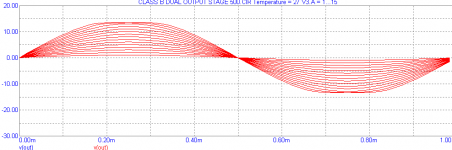
I was comparing the clipping performance of the ACP circuit to a balanced valve circuit. (The attached waveforms)
Valve amplifiers tend to sound louder than what they really are because of the soft clipping but nobody complains about, what must be, the large amounts of distortion.
So I believe the ACP amplifier will sound good while clipping too.
Also I am not totally sold on the idea that the warm valve sound is solely caused by second harmonic distortion.
I am starting to believe that humans don't hear sound like an FFT spectrum based instrument but I believe they hear the shape of a sound.
This is why some measurements don't always correlate with what people hear because the measurements are done in the wrong domain.
The flip side to spectral analysis (which states that any waveform is made up of a mixture of sine waves) is wavelet analysis (which states that a waveform is made up of a mixture of wavelets) and I believe the latter would be better at describing how a human hears, but if there was a suitable measurement tool.
But don't get me wrong the FFT is a very useful tool, a linear amplifier is a very good amplifier, but the linearity and flat and wide frequency response aren't the only design boxes that need to be ticked for your design.
Cheers
Tim
the sudden onset of hard clipping can be very bad for your speakers, but with moderately loud music there will be transients that will briefly clip an amplifier.
But I believe the clipping performance of an amplifier (especially power amplifiers) is a important criteria for it to sound good:
Very Good:
Soft Clipping
Good:
Hard Clipping - Until it clips then it sounds bad.
Bad:
Signal Inversion when clipping
Very Bad:
Unstable when clipping
I was comparing the clipping performance of the ACP circuit to a balanced valve circuit. (The attached waveforms)
Valve amplifiers tend to sound louder than what they really are because of the soft clipping but nobody complains about, what must be, the large amounts of distortion.
So I believe the ACP amplifier will sound good while clipping too.
Also I am not totally sold on the idea that the warm valve sound is solely caused by second harmonic distortion.
I am starting to believe that humans don't hear sound like an FFT spectrum based instrument but I believe they hear the shape of a sound.
This is why some measurements don't always correlate with what people hear because the measurements are done in the wrong domain.
The flip side to spectral analysis (which states that any waveform is made up of a mixture of sine waves) is wavelet analysis (which states that a waveform is made up of a mixture of wavelets) and I believe the latter would be better at describing how a human hears, but if there was a suitable measurement tool.
But don't get me wrong the FFT is a very useful tool, a linear amplifier is a very good amplifier, but the linearity and flat and wide frequency response aren't the only design boxes that need to be ticked for your design.
Cheers
Tim
Attachments
- Home
- Amplifiers
- Solid State
- Improved Diamond Buffer Design