Hallo Mr. TimS,
Some questions for You...
- I don't understand if Your last version of the buffer is a pratical realization or is on the paper( or simulator) Yet
- Is possible to use up to +/- 22V supply voltage and if yes,this need some modifications?
-What transistors should be matched and what should be in thermal contact?
-I think this improved buffer should be perfect in combination with a high performance opamp like LME49870 in Yung multiloop(or traditonal)configuration to achive an impressive headphone amplifier for low impedance type.
If this idea can be intriguing for You and the community,if You like,can You simulate the circuit and share the results maybe in a new thread?
Thank You very much in advance and best compliments for Your
very interesting circuit.
Semola
Hi Semola
The circuit has just been simulated. I fully intend to build it but i have been waiting for parts, which will arrive next week.
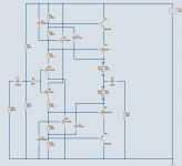
The circuit will work fine at 22V, the bias current will increase slightly to fix this increase R3 from 4k to 6k.
Ideally Q4, Q19, Q3, Q20 should be matched. The current through Q1 and Q2 will increase with temperature It could be compensated for by putting Q4 in thermal contact with Q2 and Q3 with Q1, but this is not ideal since it will ruin the matching between the Q4 and Q19 etc. A better option would be to add thermistors across R4 and R5 which will turn the bias down if Q1 and Q2 get too hot.
This is originally what I designed this circuit for, a buffer that I can add to a high performance opamp so it can drive some headphones. But I found that this circuit has superb performance all by itself.
Some of its specs:
3dB Bandwidth = 70MHz
Gain = 0.997
Input Impedance = 6M
Output Impedance = 0.065R
If R4 and R5 are 300R the bias is set to a high 220mA
total dissipation = 6.4W but
Distortion = 0.001% for +- 13V @ 1kHz into 500R
Distortion = 0.001% for +- 13V @ 1kHz into 100R
Distortion = 0.006% for +- 13V @ 1kHz into 32R
Distortion = 0.004% for +- 13V @ 10kHz into 100R
Distortion = 0.007% for +- 13V @ 10kHz into 32R
Distortion = 0.1% for +- 12V @ 1kHz into 8R
But if R4 and R5 are 150R then the bias is a lower 48mA
total dissipation = 1.4W
Distortion = 0.001% for +- 13V @ 1kHz into 500R
Distortion = 0.01% for +- 13V @ 1kHz into 100R
Distortion = 0.045% for +- 13V @ 1kHz into 32R
Distortion = 0.004% for +- 13V @ 10kHz into 500R
Distortion = 0.01% for +- 13V @ 10kHz into 100R
Distortion = 0.045% for +- 13V @ 10kHz into 32R
I have done some simulation with the buffer inside a lesser opamp's feedback loop but with worse performance, but Microcap 6 is fairly old now and doesn't include the new high performance opamps.
I checked the datasheet for the LME49870 and this buffer would be a perfect match, the bandwidth is about the same and the opamp noise and distortion is very good.
Thanks for your interest
Cheers
Tim
semola said:
- I don't understand if Your last version of the buffer is a pratical realization or is on the paper( or simulator) Yet
The circuit has just been simulated. I fully intend to build it but i have been waiting for parts, which will arrive next week.
- Is possible to use up to +/- 22V supply voltage and if yes,this need some modifications?
The circuit will work fine at 22V, the bias current will increase slightly to fix this increase R3 from 4k to 6k.
-What transistors should be matched and what should be in thermal contact?
Ideally Q4, Q19, Q3, Q20 should be matched. The current through Q1 and Q2 will increase with temperature It could be compensated for by putting Q4 in thermal contact with Q2 and Q3 with Q1, but this is not ideal since it will ruin the matching between the Q4 and Q19 etc. A better option would be to add thermistors across R4 and R5 which will turn the bias down if Q1 and Q2 get too hot.
-I think this improved buffer should be perfect in combination with a high performance opamp like LME49870 in Yung multiloop(or traditonal)configuration to achive an impressive headphone amplifier for low impedance type.
If this idea can be intriguing for You and the community,if You like,can You simulate the circuit and share the results maybe in a new thread?
This is originally what I designed this circuit for, a buffer that I can add to a high performance opamp so it can drive some headphones. But I found that this circuit has superb performance all by itself.
Some of its specs:
3dB Bandwidth = 70MHz
Gain = 0.997
Input Impedance = 6M
Output Impedance = 0.065R
If R4 and R5 are 300R the bias is set to a high 220mA
total dissipation = 6.4W but
Distortion = 0.001% for +- 13V @ 1kHz into 500R
Distortion = 0.001% for +- 13V @ 1kHz into 100R
Distortion = 0.006% for +- 13V @ 1kHz into 32R
Distortion = 0.004% for +- 13V @ 10kHz into 100R
Distortion = 0.007% for +- 13V @ 10kHz into 32R
Distortion = 0.1% for +- 12V @ 1kHz into 8R
But if R4 and R5 are 150R then the bias is a lower 48mA
total dissipation = 1.4W
Distortion = 0.001% for +- 13V @ 1kHz into 500R
Distortion = 0.01% for +- 13V @ 1kHz into 100R
Distortion = 0.045% for +- 13V @ 1kHz into 32R
Distortion = 0.004% for +- 13V @ 10kHz into 500R
Distortion = 0.01% for +- 13V @ 10kHz into 100R
Distortion = 0.045% for +- 13V @ 10kHz into 32R
I have done some simulation with the buffer inside a lesser opamp's feedback loop but with worse performance, but Microcap 6 is fairly old now and doesn't include the new high performance opamps.
I checked the datasheet for the LME49870 and this buffer would be a perfect match, the bandwidth is about the same and the opamp noise and distortion is very good.
Thank You very much in advance and best compliments for Your
very interesting circuit.
Semola
Thanks for your interest
Cheers
Tim
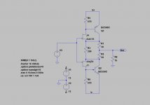
Hi Tim.
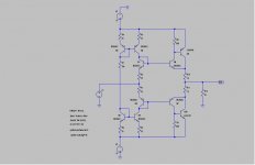
Here you can see some experimental evaluation
that I have done with Diamond follower.
- Single supply, input and output capacitor
- Resistors + Bootstrap instead of current source
- 100% Class A operation. 20 mA idle
- High impedance input ~500kOhm
* My new idea is the U2, U6 cascoding transistors.
This actually improves. But not as much as I thought.
* Bootstrap C2, C5 improves much more.
And R1, R15 should be considerably larger in value
than R2, R14 for the optimal Bootstrapping point.
* The cascode in output U1, U8 does not seem to improve things much.
Not what I have found out so far.
* C1, C6 are good for the high frequency behavior.
The performance is very good.
Even at high output voltage swing.
Say at +-20 Vrms = +- 30 Vpeak!!!!!
Lineup regards
Attachments
I would think it is very good your buffer, yes.
The great thing is it should be much, much easier
to make zero Offset, for DCin-DCout operation.
As your circuit matches NPN with NPN and PNP with PNP.
The standard Diamond has to match NPN Vbe with PNP Vbe in output.
Which can be very tricky to adjust when using DCin-DCout.
The great thing is it should be much, much easier
to make zero Offset, for DCin-DCout operation.
As your circuit matches NPN with NPN and PNP with PNP.
The standard Diamond has to match NPN Vbe with PNP Vbe in output.
Which can be very tricky to adjust when using DCin-DCout.
Its a very useful feature to have especially with headphones where one would ideally want 0 offset. It displays comparable specs to similar complexity diamond buffer. With the values shown it should be in Tim s ballpark figures. For heavier loads the diamond can be tweaked like your circuit to give exellent results. I use it to buffer the signal from car radio to amps because of the long interconnects to amps being installed in the boot and because it can drive several amps in parallel. Not really my circuit idea, saw a simplified version on the net, cant recall where and I just added the mirrors and cfp s to enhance performance.
Elegant circuits that display virtually no sound of their own, what comes in, is what comes out.
Elegant circuits that display virtually no sound of their own, what comes in, is what comes out.
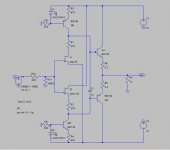
Hi Jam, it's nice looking (and even better working) circuit. Just one thing - check the J74's polarity, drain should be connected to -12V rail, although JFETs are known for their source/drain interchangeability.
I run this buffer with 5mA through JFETs (7.2 mA Idss, matched) and 7 mA through output BJTs (BC550c/BC560c) - that's enough for 1K load.
DC offset is easily adjusted with R1 or R2 and once adjusted it stays stable.
Also, I used simple CCS - two 1N4148 diodes instead of LED - it sounds great.
Best regards !
Yes, I've tried this using SK170/SJ74. Both as output buffer, and as input buffer in my le classe A headphone amp. I know most of you don't believe this, but JFETs sound different from bipolars. It's a matter of taste.jam said:Have you guys tried to use complementary jfets for the input of the buffer, Helps offset drift as you don't have to deal with base currents and could be direct coupled.
Jam
jam said:Have you guys tried to use complementary jfets for the input of the buffer, Helps offset drift as you don't have to deal with base currents and could be direct coupled.
Jam
As you very well know, jam
symmetrical JFET buffers I have used many times
")
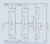
The attached circuit is one of the basic configuration
in my
No Global Feedback symmetrical JFET module
It is based on 3 parts, blocks, where the last part
is the very high input impedance Complementary JFET/BJT 'sziklai' pair buffer.
To adjust DC-offset balance in Output Buffer, you trim R5 and/or R15.
My original test setup uses 2SK170BL, BD140 and 2SJ74BL, BD139.
No problems run at 50 mA Class A, for Heavy LOADING.
My basic testings, as can be seen, used 100 Ohm load ...........

Attachments
Lineup, I really like different and unusual circuits and I think yours are the most unusual I have seen for a while.
The common gate source input for your transconductance amplifier is definitely counts as different, but I thought it would give a low input impedance and that one stage looks like a circuit I had designed as a low input impedance for a moving coil cartage pre-amplifier.
I tried the bootstrapping on my circuit instead of the constant current and the output could then swing within 1 volt of the rail but the distortion increased 2-4 times, i am not sure if the change gave me an overal win in performance, but it may be worth an extra look.
Jam, I like the idea of using complementary JFET buffers, though I thought using JFETs would increase the possibility of output offset since JFETs can have a larger variation of Vgs and Gm between devices, the difference would be harder to cancel.
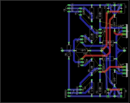
I have attached my first draft of my PCB, I hope you like it.
Cheers
Tim
The common gate source input for your transconductance amplifier is definitely counts as different, but I thought it would give a low input impedance and that one stage looks like a circuit I had designed as a low input impedance for a moving coil cartage pre-amplifier.
I tried the bootstrapping on my circuit instead of the constant current and the output could then swing within 1 volt of the rail but the distortion increased 2-4 times, i am not sure if the change gave me an overal win in performance, but it may be worth an extra look.
Jam, I like the idea of using complementary JFET buffers, though I thought using JFETs would increase the possibility of output offset since JFETs can have a larger variation of Vgs and Gm between devices, the difference would be harder to cancel.
I have attached my first draft of my PCB, I hope you like it.
Cheers
Tim
Attachments
Lineup this circuit is very clever indeed. The output buffer Ive used since 1992, it was published by JLH in his articles on preamp design. Those days I was still a student and JLH was my reference in audio design. I use them as buffers between cdplayer and monoblocks because of long interconnects leads so that I can place amps behind the speakers. I could drive headphones with them but there was some degration with low impedance ones. With the japanese parts one can ring some extra performance from this buffer. I still use my original JLH buffer but it uses junk 2n devices but even so driving amps is no problem. Together with that front end it is a very interesting circuit indeed.
Quite brilliant
Wild man with very good ideas. That one more than merits a build.
Two questions, is there any reason you choose to adjust offset with R5, R15 ?? I would it do it via R8 R13.
Whats the input impedance of the front end stages??
There is only one negative with these Jfet designs, it very difficult finding the P channel parts.
This is the JLH buffer
Attachments
CFP with JFET input and bipolar as "slave" is a favourite of mine. I can't see why it's not in wider use. I've tried it in a couple of different amps including a simple complementary amp (with a gain stage and EF run at unity gain, but otherwise similar to the picture above). I've tried it in a single end input amp and in a differential input amp, and all has improved a good deal.
Now that AKSA uses CFP input in his top of the line amp, I hope more of you give it a try.
Now that AKSA uses CFP input in his top of the line amp, I hope more of you give it a try.
lineup,
Yes I have built a version of your buffer, only two stages but I used the gates as the input and grounded the sources, (higher input z) I ran into some stability problems with the output stage but corrected it with layout and local bypassing.
Would some degeneration on the emitters of U10 and U16 help?
Regards,
Jam
Jam, no its the exactly the same circuit, JLH did it this way to adjust the offset easily. He actually used a pot for adjustment but I prefer to stay away from them. With the values shown its very close to 0 although in actual building the values may differ. With 1k loading and by decreasing R3 to say around 150 ohm to increase the current one can get very good results. Below - 140db distortion figures with second harmonic dominating and nothing after 3rd. This is simmed results but it has very good performance real time too, superior to Jfets alone and it can handle heavy loading even 100 ohms with good distortion figures. In contrast to BJT cfp theres no stability issues.
I've grown fond of the FET sound. It's warmer and gives some kind of texture and fulness to the sound. In the long run more pleasing to the ear. The downside is a slightly grainy sound compared to bipolar.jam said:nelson,
Do you like the bipolar or fet version? I have found theat the fet version requires a higher bias for the fets to sound best, and yes there is a difference betwwen the fet version and bipolar.
Regards,
Jam
- Home
- Amplifiers
- Solid State
- Improved Diamond Buffer Design