Hey there,
i recently obtained a bose 1801 from the basement of an old theatre. The thing weights 37 kg, has one huge transformer and two 14000 uF 100V caps.
After a few hours of measuring and replacing the rectifier, power cord and several times the current limiting resistor, it seems like i got a working power supply. And i haven't killed myself yet") .
.
I made some pic's, here they are: http://www.erik.in/tmp/bose1801/.
Now i got some questions:
1. When i measure the 2N5840 resistors with my cheap multimeter in diode mode, i get some values from B to E and from B to C. They are around 500, what are these values?
2. Can i use these values to match pairs?
3. The service manual says that for some models the 2N5840 can be changes to MJ15011 transistors (much easier to get), yet it also says they are not compatible. Can anybody help me there? I'm not sure about the important specs to look at when searching for replacement transistors...
4. I read alot here the last few days and one of the things was that old opamps (70's) are crap. Is this true and what could be a decent replacement for this MC1556G?
5. What are your opinions about keeping this monster as original as possible or changing it a bit for better sound/looks (like replacing some resistors and caps in the audio path, change to LED lightning)?
thanks in advance
i recently obtained a bose 1801 from the basement of an old theatre. The thing weights 37 kg, has one huge transformer and two 14000 uF 100V caps.
After a few hours of measuring and replacing the rectifier, power cord and several times the current limiting resistor, it seems like i got a working power supply. And i haven't killed myself yet
. I made some pic's, here they are: http://www.erik.in/tmp/bose1801/.
Now i got some questions:
1. When i measure the 2N5840 resistors with my cheap multimeter in diode mode, i get some values from B to E and from B to C. They are around 500, what are these values?
2. Can i use these values to match pairs?
3. The service manual says that for some models the 2N5840 can be changes to MJ15011 transistors (much easier to get), yet it also says they are not compatible. Can anybody help me there? I'm not sure about the important specs to look at when searching for replacement transistors...
4. I read alot here the last few days and one of the things was that old opamps (70's) are crap. Is this true and what could be a decent replacement for this MC1556G?
5. What are your opinions about keeping this monster as original as possible or changing it a bit for better sound/looks (like replacing some resistors and caps in the audio path, change to LED lightning)?
thanks in advance
Attachments
one thing
you need to do for sure is to check all ( and i mean all )electrolytic capacitors for leaks or values that probably gone to mars
it is very likelly that these caps are gone ...... in practice those axial caps existing in your boards are going faulty much more easy than vertical caps....
then if your machine was exposed to wet area there is also a good possibility that resistors also have other values than specified ....
resistance checks is not the method to match transistors ..... see many posts on diyaudio on how to do that .....
first you need to find out what needs to be replaced ( resistors caps )
Then you decide what quality will be your replacement parts ....
changing the electro's to something proper ( not meaning expansive or exotic ) adding bypass caps where ever needed replacing all resistors with metal film types and replacing of signal involved capacitors with something better will make a hell of a nice amp ....
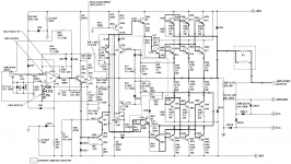
also notice in the schematic tha you have an op amp in the input ..... there might be a few things you can do there ..... find a better op amp to fit you needs
doing all these would be the place for me to stop ....trying to do more will not get you anywhere ....i allready think that these might be allredy too much and also non of it is plag and play ......messing up with input opamp might have side effects and also messing up with the out puts can be also tricky ..... i wouldnt change them i think ( have no time to check specs of the original transistors ) i would stop thouh in here .....but thats me ....may be other forum memebers can advice you on how to make your amp more ....exotic
regards sakis
you need to do for sure is to check all ( and i mean all )electrolytic capacitors for leaks or values that probably gone to mars
it is very likelly that these caps are gone ...... in practice those axial caps existing in your boards are going faulty much more easy than vertical caps....
then if your machine was exposed to wet area there is also a good possibility that resistors also have other values than specified ....
resistance checks is not the method to match transistors ..... see many posts on diyaudio on how to do that .....
first you need to find out what needs to be replaced ( resistors caps )
Then you decide what quality will be your replacement parts ....
changing the electro's to something proper ( not meaning expansive or exotic ) adding bypass caps where ever needed replacing all resistors with metal film types and replacing of signal involved capacitors with something better will make a hell of a nice amp ....
also notice in the schematic tha you have an op amp in the input ..... there might be a few things you can do there ..... find a better op amp to fit you needs
doing all these would be the place for me to stop ....trying to do more will not get you anywhere ....i allready think that these might be allredy too much and also non of it is plag and play ......messing up with input opamp might have side effects and also messing up with the out puts can be also tricky ..... i wouldnt change them i think ( have no time to check specs of the original transistors ) i would stop thouh in here .....but thats me ....may be other forum memebers can advice you on how to make your amp more ....exotic
regards sakis
Thanks for the replies, it looks like i'll have to rebuild almost the complete PCB then . Or better even, etch a new one, that's probably quicker than desoldering and repairing the thing.
It could be fun to build a board using this design, upgrade it a bit with more modern solid state and listen to the difference between the channels.
I've got some reading to do, i'll be back.
. Or better even, etch a new one, that's probably quicker than desoldering and repairing the thing. It could be fun to build a board using this design, upgrade it a bit with more modern solid state and listen to the difference between the channels.
I've got some reading to do, i'll be back
.jaycee said:To be honest with the age of all those parts, i'd be inclined to say gut it, and built the Leach Super Amp into the case. From the schematic, it looks very similar anyway.
+1. But with only +/-85v rails and 6x MJ15024/5, you could just run a straight parallel output stage. Did this with mine back in '90. The new design also used an op-amp input stage (LF412) and a push-pull VAS, making it more similar to the BGW amps.
hi all. this thread is old. but its titled bose 1801 repairs. last post was october 2008. what happened nobody owns 1801's no more? or 1801's are not breaking? anyway, i have this 1801 that the left uv meter is not working. the right uv meter works just fine. the led meters works fine also. i get audio on both channels. i have a digital multimeter. i love the uv meters and would like to get this working again. i think i can order another generic working uv meter just use the inner parts like the coil that makes the needle move. but first i need help to fix the problem that killed my uv meter.
thanks.
thanks.
They are around .500 volts, the forward voltage of the b/c and b/e junctions considered as diodes. They indicate that the transistors are probably working.1. When i measure the 2N5840 resistors with my cheap multimeter in diode mode, i get some values from B to E and from B to C. They are around 500, what are these values?
Hello ,
Is U1 the input op-amp mc1556g? Can that be substitute with lme49710ha?
Thanks
I owned an 1801 and did just that,subbed the 1556g for a 49710 and after that, turn off and turn on resulted in loud "pop" sounds thru my speakers.The 49710 is too fast,you need a slower op amp.Not sure what to recommend as I sold the unit as it was.
One more thing,a LOT of the old carbon resistors were way out of tolerance on mine,I replaced most of them.In addition,there is a factory fix for a zener/resistor combination that must be done.If you don't do this you run a high risk of blowing the amp up,and i'm not kidding.You can google the wording and find the factory procedure.You must do this or at least confirm that it has been done.
Those zener-resistor shunt regulators for the op amp front ends were THE most common failure mode for gently-used amps of this type/era. It just cooks the PCB and oxidizes the joints, especially after decades. Higher wattage resistors should be used, along with ventilation. Higher R can be used too, but there is a limit of how high it can go. I quit using shunt regs in my own designs, because it is easy to heat sink a full pack TO-220 transistor instead of a 5 watt sand-box resistor.
- Home
- Amplifiers
- Solid State
- bose 1801 repairs