I have had several months of listening to the original amp . Although I didn't put it in a case, I used it every time I did any work in my lab. I have had a few different amps to compare to it, mostly DIY, but none have been it's equal, including my Yamaha htr.
This may be due to it's high power - I don't have anything else that can put out more than 100 watts. The difference is mainly in the bottom end - there is more authority to the bass, it seems more solid. This could be a delusion on my part, but I'm usually tough on my creations, not giving credit where it's not warranted.
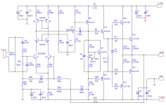
In any case, I have a six channel amp project planned and I thought I would put my effort to use by using this design for the amp modules. I set about refining the circuit, subtle changes to improve performance, lower distortion. I have changed the output devices to MJL21193/94, as I have many of these and would need 12 of each for the six modules. Other changes that I'll be going through and looking for advice on.
The new schematic:
This may be due to it's high power - I don't have anything else that can put out more than 100 watts. The difference is mainly in the bottom end - there is more authority to the bass, it seems more solid. This could be a delusion on my part, but I'm usually tough on my creations, not giving credit where it's not warranted.
In any case, I have a six channel amp project planned and I thought I would put my effort to use by using this design for the amp modules. I set about refining the circuit, subtle changes to improve performance, lower distortion. I have changed the output devices to MJL21193/94, as I have many of these and would need 12 of each for the six modules. Other changes that I'll be going through and looking for advice on.
The new schematic:
Attachments
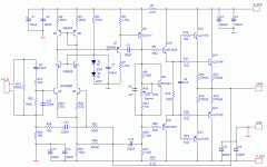
The changes...
I started by not using the LM394 super-matched pair. As nice as these are, they are pricey. It would have been more than $60 alone for 6 of these. I went with the BC550 and kept the rest of the front end intact, except for some resistor values.
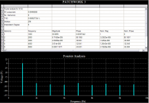
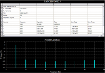
I played with multisim trying different things to either improve performance or reduce component count. I recently learned how to run the fourier analysis which will extend the precision of the THD figures. This has made a big difference.
Here's a look at it as it was before. This very good performance was proven on a real distortion analyzer last January.
I started by not using the LM394 super-matched pair. As nice as these are, they are pricey. It would have been more than $60 alone for 6 of these. I went with the BC550 and kept the rest of the front end intact, except for some resistor values.
I played with multisim trying different things to either improve performance or reduce component count. I recently learned how to run the fourier analysis which will extend the precision of the THD figures. This has made a big difference.
Here's a look at it as it was before. This very good performance was proven on a real distortion analyzer last January.
Attachments
In the front end I increased current by changing R27 from 20K to 12K. I increased R2 and R3 to 360 ohms and lowered the emitter resistors to 33 ohms.
This has ~4.3mA through the front end.
A slight improvement as shown below, about .0001% less. Every little bit helps, right?
This has ~4.3mA through the front end.
A slight improvement as shown below, about .0001% less. Every little bit helps, right?
Attachments
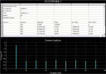
Further changes were to more than double R4 from 7K to 15K. I deleted R6, increased R5 to 4.7K up from 1K. I deleted the emitter resistor of the VAS (R7 in the old schematic) as unnecessary. Interestingly, removing this 10 ohm resistor made an impact on the THD.
A further overall reduction:
A further overall reduction:
Attachments
Here's one I didn't expect. Changing the drivers load resistor from 55 ohm to 150 ohms reduced THD by .0002% alone.
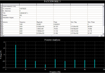
R28, "bootstrap" resistor is now 450K - the best value. A reduction of .0001% at the test power (~56 watts into 8 ohms) and nearly .0003% at 20Khz - incredible really.
I also spent some time trying a previously attempted feedback to the cascode. This did nothing but increase distortion, so I guess I exercised prescient vision when I axed it before.
The result of these changes is an overall reduction in THD by more than .0003%. If this is accurate in real terms is debatable. Whether this reduction is audible is highly unlikely, but there were several improvements made beside the THD figure. Parts were eliminated - this is good. Current through the drivers was reduced without adverse effect (verified with the real amp, no problem into a low impedance load).
Thoughts on my changes? Ideas for more?
Last of these boring graphs:
Attachments
Nice design! 
And nice THD graphs... But hey, 0.0006% vs. 0.0005% vs. 0.0004% tells nothing improvement. And the THD alone is not enough to desribe the quality of an amplifier!
I'd happy to see some square-wave & slew-rate & IM measurements, if they are available. Maybe there is room for a real improvement there!
megajocke said:Why such a low voltage for the input stage cascode? Weird stuff might happen on input overload.
Output stage base resistors can probably be reduced from 10 ohms making current sharing less dependent on hfe.
Hi mega,
I have 3.87Vdc now from the 2 standard green LEDs. I went with this to avoid a zener in this position (noisy?).
What do you suggest to get the voltage up? Another LED maybe OR I have some high intensity blue ones that have a forward voltage of ~2.75. I will try those in the prototype.
I was going to experiment with deleting the base stoppers to see if the design is stable without them.
Do you have any other suggestions? My devices are not fancy, popular choices around here. My outputs are rather slow at 4Mz.
ferencz said:Nice design!
And nice THD graphs... But hey, 0.0006% vs. 0.0005% vs. 0.0004% tells nothing improvement. And the THD alone is not enough to desribe the quality of an amplifier!
I'd happy to see some square-wave & slew-rate & IM measurements, if they are available. Maybe there is room for a real improvement there!
Thank you!
Lacking in depth knowledge, I use the THD figure to tell me if I'm doing something completely stupid. I figure if it goes lower, I'm doing something right.
")
I did some testing of the original amp in the first thread. Some of the results start
here.
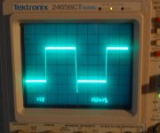
A few square wave shots too.
When I get the prototype for this one road-worthy, I'll do some testing.
Having lived with the original for a few months, I can say that it is a fine sounding amp. Fast and accurate. Powerful and very stable. I have made some changes on this one, but nothing (I hope) that will undo my good results from before.
Do you have any suggestions for possible improvements?
Do you have any suggestions for possible improvements?
Your amp is already a "state-of-art" design among the amplifiers using the "Lin" circuit topology.
But, as on every side of life there is always room for improvement!
The only mod I could recommend now is to change the drivers to MJE15032/33. The reason is that in practice I found that related the MJE15030/31 pair there is always a huge Hfe difference between PNP and NPN device.
PS:: I visited the quoted thread. You made excellent work! Excellent!
Anyway that's a great thread with many great informations!
MJL21193 said:
Hi mega,
I have 3.87Vdc now from the 2 standard green LEDs. I went with this to avoid a zener in this position (noisy?).
What do you suggest to get the voltage up? Another LED maybe OR I have some high intensity blue ones that have a forward voltage of ~2.75. I will try those in the prototype.
I was going to experiment with deleting the base stoppers to see if the design is stable without them.
Do you have any other suggestions? My devices are not fancy, popular choices around here. My outputs are rather slow at 4Mz.
I'd probably use zeners anyway as this noise will have a pretty hard time getting into the circuit and be amplified as the differential stage has very good rejection when voltage changes the same on both collectors. Another option is just using a resistive divider with a bypass cap. I'd probably like to have a little more voltage than possible with LEDs, at least 12-15V or so.
I'd probably reduce the output stage base resistors to 2 ohms or something similar. It might even be possible to remove them completely like you say but I believe the only thing gained is a lower component count.
ferencz said:
But, as on every side of life there is always room for improvement!
The only mod I could recommend now is to change the drivers to MJE15032/33. The reason is that in practice I found that related the MJE15030/31 pair there is always a huge Hfe difference between PNP and NPN device.
Thank you again,
The drivers I have were supposed to be matched when I bought them 3 years ago. I have ten sets of these.
I'm actually thinking of using the 2SA1011/2SC2344 as the drivers and changing out the VAS to the 2SA1381. These are higher gain, higher frequency devices.
Any thoughts on the 2STC5200 / 2STA1943 as outputs? These are the ST version of the 2SA5200/1943 but with higher gain. These are faster than the MJL21193/94 and about half the price.
megajocke said:
I'd probably use zeners anyway as this noise will have a pretty hard time getting into the circuit and be amplified as the differential stage has very good rejection when voltage changes the same on both collectors. Another option is just using a resistive divider with a bypass cap. I'd probably like to have a little more voltage than possible with LEDs, at least 12-15V or so.
I'd probably reduce the output stage base resistors to 2 ohms or something similar. It might even be possible to remove them completely like you say but I believe the only thing gained is a lower component count.
As much as 15V? I'll try it in the sim. Thanks.
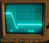
What could be the cause of this overshoot on the squarewave? Also quite a slope on the downward cycle of the wave. Here's a picture of the amp with a 20kHz squarewave.
Attachments
megajocke said:
Another option is just using a resistive divider with a bypass cap. I'd probably like to have a little more voltage than possible with LEDs, at least 12-15V or so.
I did that with good results. Better THD performance also (yeah, I know that means nothing).
Updated the schematic to show that change. This is what I like - a change that simplifies, improves and lowers the component count.
Attachments
MJL21193/94 > 2SC5200/2SA1943
Then you'll need more pairs to stay on the safe side when amp is loaded with 4R speaker (SOA!). Three, or even four pairs will needed!
Very good idea, strongly recommended!
I'd "play" with the compensation circuit (here it's a lag-Miller-capacitor, namely C5). Try 47pF and then 150pF. Maybe some lead compensation (10pF from the VAS's output to Q2's base) helps. Inserting the lead capacitance will increase the hi-freq THD a bit!
Or maybe C9 has wrong value? Try 100nF!
Then you'll need more pairs to stay on the safe side when amp is loaded with 4R speaker (SOA!). Three, or even four pairs will needed!
I'm actually thinking of using the 2SA1011/2SC2344 as the drivers and changing out the VAS to the 2SA1381.
Very good idea, strongly recommended!
What could be the cause of this overshoot on the squarewave? Also quite a slope on the downward cycle of the wave. Here's a picture of the amp with a 20kHz squarewave.
I'd "play" with the compensation circuit (here it's a lag-Miller-capacitor, namely C5). Try 47pF and then 150pF. Maybe some lead compensation (10pF from the VAS's output to Q2's base) helps. Inserting the lead capacitance will increase the hi-freq THD a bit!
Or maybe C9 has wrong value? Try 100nF!
MJL21193 said:
Thank you again,
The drivers I have were supposed to be matched when I bought them 3 years ago. I have ten sets of these.
I'm actually thinking of using the 2SA1011/2SC2344 as the drivers and changing out the VAS to the 2SA1381. These are higher gain, higher frequency devices.
Any thoughts on the 2STC5200 / 2STA1943 as outputs? These are the ST version of the 2SA5200/1943 but with higher gain. These are faster than the MJL21193/94 and about half the price.
As much as 15V? I'll try it in the sim. Thanks.
What could be the cause of this overshoot on the squarewave? Also quite a slope on the downward cycle of the wave. Here's a picture of the amp with a 20kHz squarewave.
Assymetric slew rate suggests something is wrong with the current mirror. Try lowering R2, R3 - they drop quite a bit of voltage as it is now and probably doesn't leave enough headroom for the transistors in the mirror to work correctly.
What is the rail voltage?
ferencz said:MJL21193/94 > 2SC5200/2SA1943
Then you'll need more pairs to stay on the safe side when amp is loaded with 4R speaker (SOA!). Three, or even four pairs will needed!
Depends on rail voltage...
You can go up to 60V rails or so with two pairs and 4 ohm loads. Three pairs if you want to keep down Ice where they are more linear.
Fairchild has a version to both under the name 2sc5200/2sa1943 and FJL4215/FJL4315. These are cheap from digikey. Actually the originals are cheaper than the ST copies even...
4 pairs is enough for 80V (sagging) rails and 2 ohms if you build an amplifier without insulation between transistors and heatsink.
Nico Ras said:Hi John,
Experiment with a 100 - 470 uF cap between the emitters of Q1 and Q2 and have a look see what it does with your already minuscule distortion. The results may be interesting in future designs.
Kindest regards
Nico
That would destabilize the amp if it's compensation is optimal.
I believe it is better to have emitter resistors there linearizing the input stage and use a high standing current to get the same transconductance but much more linear.
megajocke said:
That would destabilize the amp if it's compensation is optimal.
I believe it is better to have emitter resistors there linearizing the input stage and use a high standing current to get the same transconductance but much more linear.
It actually nulls the emitters at ac and reduces distortion. A trick used by Dan Augustino in the mid seventies and I believe still use it today. I have used it in many of my designs both private and commercial with quite good results.
ferencz said:MJL21193/94 > 2SC5200/2SA1943
Then you'll need more pairs to stay on the safe side when amp is loaded with 4R speaker (SOA!). Three, or even four pairs will needed!
I'd "play" with the compensation circuit (here it's a lag-Miller-capacitor, namely C5).
Hi,
Tried the miller cap - no go.
Yes, lower power devices, but the load for this amp will be 8 ohms.
Nico Ras said:Hi John,
Experiment with a 100 - 470 uF cap between the emitters of Q1 and Q2 and have a look see what it does with your already minuscule distortion. The results may be interesting in future designs.
Thanks Nico,
Glad you are here. I will try this as I have seen it elsewhere too (KSA-50?). Your advice, as usual, is always valuable.
Do you have any other ideas That could improve this project?
megajocke said:
Assymetric slew rate suggests something is wrong with the current mirror. Try lowering R2, R3 - they drop quite a bit of voltage as it is now and probably doesn't leave enough headroom for the transistors in the mirror to work correctly.
BINGO! That's the beauty of this forum - there is someone who knows EXACTLY what your problem is. Thank you very much Mega, I lowered the R's to 110 ohms and all is well. Perfectly symmetrical squarewave at 20kHz. I'll post some pics soon.
megajocke said:
What is the rail voltage?
Depends on rail voltage...
You can go up to 60V rails or so with two pairs and 4 ohm loads. Three pairs if you want to keep down Ice where they are more linear.
Fairchild has a version to both under the name 2sc5200/2sa1943 and FJL4215/FJL4315. These are cheap from digikey. Actually the originals are cheaper than the ST copies even...
4 pairs is enough for 80V (sagging) rails and 2 ohms if you build an amplifier without insulation between transistors and heatsink.
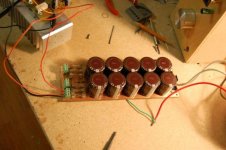
The rail voltage for this is 56 - drooping to 54VDC under full load with a fairly stiff power supply (see pic below). 23500uF/rail but this PS will be shared by two other amps. There will be two PS in total, one 750VA transformer and 6 amp modules.
I saw the ST devices are higher gain, that's why I choose them. If this is no big deal, I'll use the Fairchild ones (actually just checked and they have the higher gain also)
Attachments
Nico Ras said:
It actually nulls the emitters at ac and reduces distortion. A trick used by Dan Augustino in the mid seventies and I believe still use it today. I have used it in many of my designs both private and commercial with quite good results.
If you design around it I guess you could make it work in an excellent way. In a symmetric circuit with two LTP:s (one per rail) it would be useful as it lets you use large emitter resistors for good DC balance in the input stage.
Though, if you take an optimized design which was designed around an LTP with emitter resistors it will increase the open loop gain bandwith product possibly making the amplifier unstable.
MJL21193 said:
BINGO! That's the beauty of this forum - there is someone who knows EXACTLY what your problem is. Thank you very much Mega, I lowered the R's to 110 ohms and all is well. Perfectly symmetrical squarewave at 20kHz. I'll post some pics soon.
Glad that I could help
The rail voltage for this is 56 - drooping to 54VDC under full load with a fairly stiff power supply (see pic below). 23500uF/rail but this PS will be shared by two other amps. There will be two PS in total, one 750VA transformer and 6 amp modules.
I saw the ST devices are higher gain, that's why I choose them. If this is no big deal, I'll use the Fairchild ones (actually just checked and they have the higher gain also)
Then you will have good margin with 2 pairs. That is a pretty stiff supply, looks nice too
- Status
- This old topic is closed. If you want to reopen this topic, contact a moderator using the "Report Post" button.
- Home
- Amplifiers
- Solid State
- Patchwork Reloaded: Circuit Optimization and Board Layout.