megajocke said:If you have trouble with sticking on the bootstrap side you can add a diode to clamp the voltage so it can only go outside the rail by 1 diode drop. Then you put one diode in series with the feed from bootstrap circuit to VAS so that the voltage on the driver base/bias spreader is clamped at rail voltage. This prevents saturation in the driver transistor.
Hi Mega,
I partially understand what you are saying here, but it would help me if you could clarify.
Would I put a clamp from the top of the bootstrap (cathode) back to the negative rail (anode)?
Then I'm puzzled by the second diode. In series with the bias generator?
I have the near total lack of competent understanding and the simulators contrary refusal to treat diodes appropriately working against me.
Full power test reveals maximum 35Vrms output before clipping into 8 ohm dummy load - 153 watts if my math is sound.
This is more than the original. More is better, right...
")
You know, I'm a technickel boy, but not a technicsion.

Attachments

No one has made any comment on my "findings" back in post #194. I thought this was some provocative stuff - fuel for further discussion on the merit of using the bootstrap.
Oh well.
I'm running the amp at full power supply, doing some casual listening.

Even in this untidy state, it is dead silent. When I connected it to the speaker, I had to check to make sure it was plugged in and working. I couldn't hear anything from the speaker.
I asked my 18 year old son to have a listen, given that my ears have had years of construction noise abuse. He could not hear anything at all - no hiss. So much for PSRR.
Still no Zobel.
Oh well.
I'm running the amp at full power supply, doing some casual listening.
Even in this untidy state, it is dead silent. When I connected it to the speaker, I had to check to make sure it was plugged in and working. I couldn't hear anything from the speaker.
I asked my 18 year old son to have a listen, given that my ears have had years of construction noise abuse. He could not hear anything at all - no hiss. So much for PSRR.
Still no Zobel.
andy_c said:
Hi Glen,
Here's some experiments I've done in the simulator and what I've found. This used a configuration like the "Blameless" amp.
1) Configuration 1: Input and output stages modeled as ideal controlled sources, and VAS the same as the real design. Vary input stage gm and VAS Cdom simultaneously so as to keep the GBW constant. Look at full power 20 kHz THD.
2) Configuration 2: VAS and output stages modeled as ideal controlled sources, with input stage the same as the real design. The idealized VAS input impedance, transconductance and input DC offset from the rail were made the same as the actual VAS. Vary input stage gm and VAS Cdom simultaneously so as to keep the GBW constant. Look at full power 20 kHz THD.
For configuration 1, using reasonable values of Cdom (< 200 pF), the larger Cdom was made, the lower the distortion was. I assume that the increase in the loop gain of the Miller loop due to increasing Cdom was responsible - apparently winning out over the increased VAS loading.
For configuration 2, the larger Cdom was made, the larger the distortion was. Clearly this was the result of the capacitive loading of Cdom on the input stage. Input stage distortion was very low, but this wasn't achieved until I used bootstrapped cascoding of the input stage.
Now suppose the whole amp were simulated, starting with larger than usual input stage emitter degeneration and small Cdom. Suppose you simultaneously decrease emitter degeneration and increase Cdom to keep GBW constant. My guess was that the 20 kHz full power THD would keep decreasing up to the point where input stage distortion started to overtake VAS distortion. Then, as further decreases in input stage emitter degeneration were made, the distortion would begin to increase again. This is exactly what happened. I stepped Cdom over a list of standard capacitor values, recomputing input stage RE at each step. There was a combination of Cdom and input stage RE that gave the best 20 kHz THD. For larger or smaller Cdom (with RE adjusted appropriately), the full power 20 kHz THD increased. So I ended up using the Cdom and RE that were optimized in this way. For this specific design, Cdom was 68 pF - nothing at all radical.
Hi Andy.
Nice experiment. However I suspect that (so long as Cdom is adjusted to keep the GBW constant, which it should be) that the LTP degeneration can be varied over quite a reasonable range without drastically effecting the HF distortion. Another advantage of a reduced Cdom with lower LTP gm is increased slewing.
Cheers,
Glen
G.Kleinschmidt said:
Hi Andy.
Nice experiment. However I suspect that (so long as Cdom is adjusted to keep the GBW constant, which it should be) that the LTP degeneration can be varied over quite a reasonable range without drastically effecting the HF distortion. Another advantage of a reduced Cdom with lower LTP gm is increased slewing.
Cheers,
Glen
My simulation agrees with this. Increasing degeneration in the LTP while decreasing the Miller cap to 47pF brings distortion back to nearly where it was before. I haven't compared the HF yet.
Glen do you think stability would suffer?
G.Kleinschmidt said:Nice experiment. However I suspect that (so long as Cdom is adjusted to keep the GBW constant, which it should be) that the LTP degeneration can be varied over quite a reasonable range without drastically effecting the HF distortion. Another advantage of a reduced Cdom with lower LTP gm is increased slewing.
Exactly. The variation of distortion wasn't drastic at all. This was an attempt at optimization.
Still, with ideal controlled sources used for the VAS and output stage, I was surprised at how little distortion the non-ideal input stage produced. Yet the results for the same experiment without bootstrapped cascoding of the input stage were disappointing.
Also, a slew-enhanced input stage, as I think you're using in some of your designs, can decouple these two design tradeoffs. IOW, you can get your optimized 20 kHz full power THD, yet still have high slew rate.
MJL21193 said:My simulation agrees with this. Increasing degeneration in the LTP while decreasing the Miller cap to 47pF brings distortion back to nearly where it was before. I haven't compared the HF yet.
Glen do you think stability would suffer?
That's the idea. If you scale the input stage emitter resistor up by a factor of K, also scale the Cdom down by that same factor. That will keep stability constant. In practice, you'll want to scale the Cdom to the next standard value, then choose the input stage RE appropriately. Repeat until golden brown
. Stated another way, the product of RE and Cdom should stay constant.Look at 20 kHz THD at full power in the simulator when doing this. Use the highest input stage RE that does not degrade full power 20 kHz THD significantly.
andy_c said:
That's the idea. If you scale the input stage emitter resistor up by a factor of K, also scale the Cdom down by that same factor. That will keep stability constant. In practice, you'll want to scale the Cdom to the next standard value, then choose the input stage RE appropriately. Repeat until golden brown
Look at 20 kHz THD at full power in the simulator when doing this. Use the highest input stage RE that does not degrade full power 20 kHz THD significantly.
My simulator must be having a hormonal imbalance - it's not giving me reliable data tonight.
I've attempted to run several 20k fundamental sims; some finished and most didn't. I don't know why. Maybe she's too tired.
Anyway, from what I did get: lower Cdom and higher degeneration in the differential pair seems to win out at high frequency. Unreliable results show a marked decrease in distortion at 20k. A virtual tie at lower frequencies.
Also, jcx' idea for tyeing the bootstrap cap to the Q11 emitter drives distortion further down.
Looks like a schematic update is on the way and some changes to the board layout.
jcx said:I don't think I can take credit for bootstrapped tail current souces, they predate my birth date
If I were modding what I see in the last schematic I would go for more current gain by using cfp driver stage and high enough bias that it would always be in solid Class A
Just giving you credit for posting that simple example some time ago. Do you know when it was first used? I have a mild interest in the history behind it.
Interesting, that you suggest a CFP driver as I have an interest in CFP stages with gain and was moving toward CFP in the driver with EF for final outputs. I was not aware of this being done before but I believe John showed one in the original thread that he adapted from Rod E's site. I've also seen reference to the Marantz 250 which IIRC also uses a CFP driver however in an awkward arrangement as I recall.
Pete B.
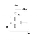
megajocke said:This is what I had in mind. Don't know if it's really needed though.
D1 needs to be able to take full rail-to-rail voltage just like the VAS clamp diode. D2 is never reverse biased, 1n4148 or similar should work for that one.
It would be nice to get rid of that last small glitch on the negative going side. I believe that it is a sign of cross conduction - John you might want to probe the driver and output collector current with a scope in simulation as there is probably a spike right before the glitch in the output. The boosted supply from the bootstrap provides enough drive to push the drivers and/or outputs into saturation.
Pete B.
John,
I made an error, oversimplifying the calculation of the input stage emitter resistor when changing Cdom. Here's a much more accurate formula.
First, calculate re=26e-3/IC
where IC is the per-transistor DC collector current of the input stage (not the total tail current). The IC value should be in units of Amps.
Let RE1 be the original input stage emitter resistor value (=33).
Let C1 be the original Cdom value (=100e-12, units of Farads).
Let C2 be the new Cdom value (units of Farads).
Let RE2 be the new input stage emitter resistor.
Pick C2. Then calculate the new emitter resistor RE2 from this formula:
RE2 = re*(C1/C2-1)+RE1C1/C2
My original formula assumed re to be much smaller than RE1. But with RE1 of 33 Ohms, this is not actually the case. Sorry for the confusion.
CFP drivers have been used for quite some time, a good example is roenders excellent RMI FC100 amp here in these threads. Pior to that I found it used by Harmon K in AV recievers of 7 Years back. Works very well, high input impedance pretty easy to stabilise. I have been using a BJT Mosfet cfp which is even better but here stability is tricky to achieve.
megajocke said:This is what I had in mind. Don't know if it's really needed though.
D1 needs to be able to take full rail-to-rail voltage just like the VAS clamp diode. D2 is never reverse biased, 1n4148 or similar should work for that one.
Thanks! I thought that was the scheme, but it's nice to be sure.
A schematic update shortly. I want to try out this clamp and the other changes that I have planned first.
AndrewT said:This is becoming a reference paper on how to design a bootstrapped Power Amp.
Keep up the good work/experimentation.
When you're all done I'll convert the thread to printable and save the result.
Thanks Andrew,
That's the nicest thing you've ever said to me!
I am merely the assembly line worker, putting all of these brilliant contributions from the participants here together. Nails, screws and glue - that's me.
I am extremely pleased with the results so far. It's been well worth the effort.
PB2 said:
It would be nice to get rid of that last small glitch on the negative going side. I believe that it is a sign of cross conduction - John you might want to probe the driver and output collector current with a scope in simulation as there is probably a spike right before the glitch in the output. The boosted supply from the bootstrap provides enough drive to push the drivers and/or outputs into saturation.
Hi Pete,
Not seeing any spike. This isn't a surprise since the sticking in the upper didn't show in the sim. One of the definite limitation (at least in my ability to use it to reveal these problems).
It's mild and I'm hoping that the planned changes will take care of it.
andy_c said:John,
I made an error, oversimplifying the calculation of the input stage emitter resistor when changing Cdom. Here's a much more accurate formula.
First, calculate re=26e-3/IC
where IC is the per-transistor DC collector current of the input stage (not the total tail current). The IC value should be in units of Amps.
Let RE1 be the original input stage emitter resistor value (=33).
Let C1 be the original Cdom value (=100e-12, units of Farads).
Let C2 be the new Cdom value (units of Farads).
Let RE2 be the new input stage emitter resistor.
Pick C2. Then calculate the new emitter resistor RE2 from this formula:
RE2 = re*(C1/C2-1)+RE1C1/C2
My original formula assumed re to be much smaller than RE1. But with RE1 of 33 Ohms, this is not actually the case. Sorry for the confusion.
Wow, lots of mind boogling math! Help!!
Nah, I think I can handle it.
So:
re=.026/.00242
re=10.74
RE2=10.74*1.28+70.212
RE2=83.9592
Hmm, just 84ohms? This is to maintain the present pole (stability)? Should I factor in capacitance from the Baker clamp, or is this negligible?
I'm going to try these changes, but I haven't a 47pF mica. I can either parallel 3-15pF or series 2-100pF to get close to the correct value. Is this advisable?
homemodder said:CFP drivers have been used for quite some time, a good example is roenders excellent RMI FC100 amp here in these threads. Pior to that I found it used by Harmon K in AV recievers of 7 Years back. Works very well, high input impedance pretty easy to stabilise. I have been using a BJT Mosfet cfp which is even better but here stability is tricky to achieve.
I tried the CFP in a rather high power sub amp.. I wound up abandoning the configuration, due to instability.
I had a look at that thread a while back, the problem there is that the cfp has to be much faster than final outputs. Then again you got 8 pairs which might influence as well. Base stopper resistors of around 3 to 5 ohm on the outputs shoud kill the oscilations. With the transitors you have 2sc3503 and 2sa1011 would be excellent combination for the cfp if you want to try although you have very good performance already as is.
MJL21193 said:RE2=10.74*1.28+70.212
RE2=83.9592
Hmm, I get 82.3 Ohms, which rounds to 82.5 for the nearest 1 percent standard value. I get 1.128 rather than your 1.28.
This is to maintain the present pole (stability)?
This changes both the DC gain and the open-loop bandwidth, but does so in such a way as to keep their product (the gain-bandwidth product) the same as it was before. This keeps the stability the same.
Should I factor in capacitance from the Baker clamp, or is this negligible?
It's negligible for the BAV21 but not for the diode you have on hand.
I'm going to try these changes, but I haven't a 47pF mica. I can either parallel 3-15pF or series 2-100pF to get close to the correct value. Is this advisable?
The parallel case might be better due to a lower inductance. Try to cluster them together as closely as possible.
homemodder said:I had a look at that thread a while back, the problem there is that the cfp has to be much faster than final outputs. Then again you got 8 pairs which might influence as well. Base stopper resistors of around 3 to 5 ohm on the outputs shoud kill the oscilations. With the transitors you have 2sc3503 and 2sa1011 would be excellent combination for the cfp if you want to try although you have very good performance already as is.
For an amp like that, the primary goal after getting it working is getting it stable. Too much power, components and time at risk.
Beside, the better linearity in the output stage is lost on such an amp. It currently operates from ~15Hz to 60Hz.
I would consider taking another shot at the CFP in an amp of this power level though, but like you've said - would anything truly be gained?
andy_c said:
Hmm, I get 82.3 Ohms, which rounds to 82.5 for the nearest 1 percent standard value. I get 1.128 rather than your 1.28.
It's negligible for the BAV21 but not for the diode you have on hand.
The parallel case might be better due to a lower inductance. Try to cluster them together as closely as possible.
Ok, I guess my math was not up to the task
Speaking of the BAV21, Digikey only has the surface mount in small price break. B&D has them, and I'd like a few more 2SA1011/C2344's so I'll order them there.
Now then, paralyzed by fear of ruining the good work I have already done, I took a break and watched a movie. Being too broke to have any beer to bolster my confidence (new components? or beer? New components, or beer?? New components), I started in with trepidation.
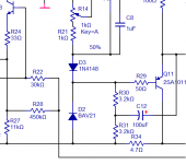
I figured I'd do one thing at a time, keeping an eye on results. Thing 1: I've added the two clamping diodes to the bottom. Shown below (no, I haven't moved the bootstrap cap to feed from the lower driver yet).
Something is not right. I connected the amp to my variable supply, starting with 5 volts and dialing up. It's drawing too much current. My supply has a 50 amp ammeter showing this is drinking more than half an amp with +/-9V supply and no load.
I thought it's oscillating. Nothing showing on the scope, but I connect the dummy load with a Zobel tacked on. No improvement.
I check and double check and of course triple check, but I haven't made one of my patented bone-headed mistakes. I cant' leave it running long, as It's not on the heatsink, but I did measure the DC at the bases of the drivers - 1.3+V on both. This is more than there should be (I think).
I gave it a signal and it handled that fine. Clips flat, but it is just 9V supply.
Any thoughts on what is happening?
Attachments
MJL21193 said:
Any thoughts on what is happening?
I'll answer my own question: Vbe multiplier was thrown off by this clamp arrangement. It was drawing current too over bias the outputs. I adjusted the Vbe pot and brought it back down to normal.
I'm going to bring the voltage up to +/-30V...
...It won't go there. The Vbe resistor values will need to be changed as I can't adjust the pot low enough.
- Status
- This old topic is closed. If you want to reopen this topic, contact a moderator using the "Report Post" button.
- Home
- Amplifiers
- Solid State
- Patchwork Reloaded: Circuit Optimization and Board Layout.