Hi all.
About 5 years ago I came up with this design, which I modelled (I can't remember which SPICE program... may have been MultiSim) and which seemed ok in the virtual world. Now bear in mind, I am no electronics engineer and I was limited to the parts bin of that program. Hence the tubes and some of the semiconductors used.
My design goal was not audio nirvana, but rather to create an amplifier which met the following criteria:
- it should be a hybrid, because I have a real soft spot for tubes and I like their sound
- it should be a balanced design of unique topology, for it's own sake, just to be 'different' - yes, I know some will think that's silly, but I wanted something distinct
- I didn't want any long-tailed pairs
- it should be a current-feedback design, with the tube VAS specifically excluded from the loop.
Ok, so here it is and my questions are:
What do the learned, experienced engineers think, honestly?
What constructive criticisms or tips could you guys offer?
Since I'm now sans SPICE, which simulation package would you guys recommend, bearing in mind the tubes, preferably freeware?
Attachments
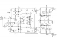
I see a clever input, using Triodes + P-MOS to produce complementary signals
for the VAS Q2 and Q3.
P MOSFET are IRFD9120 .. which are in IC chip format
The idea looks good to me.
Hybrids are often interesting.
I would try to simplify = less many transistors.
And reduce output power, to suit my own needs.
But for +-60 V supply and at such output powers, those many devices may be needed.
As I do not know anything about 7199P and I am not experienced with tubes:
- How does those 7199P work at 100 Volt?
- What current will run in those 2 Triodes?
DrG
You are definitely a clever guy with good understanding of how disrete elemtents work, nice design with number of uncommon stages.
However I have some troubles understanding the feedback loop. First it seems to me R11 and R12 are useless, because are in series with high impedance current mirror ouput.
Next, the whole gain of the circuit seems to be (PMOS-to-triode transconductance)*22kOhm, is that your goal?
This will well result in symmetric triode non-linearity leaving the transistor stage reasonably linear.
Another issue is the lack of frequency compensation of the feedback loop, are you sure it is not needed here? If not are you considering adding extra miller camacitance to common emitter stages or connecting a emitter connection between Q17/Q18 to a capacitor to ground?
What output stage bias do you plan?
Best Regards,
Adam
Hello lineup!
The 7199 was the only suitable tube from the very limited parts bin in the spice program I used. And I don't know enough to modify spice models myself... The same is true for the IRFD's, I just used what was available and electrically suitable.
The tubes I would like to use (because I have many hundreds of them) are subminiature 5840's, possibly triode connected or maybe 6111's. Not sure of the currents right now, will have to check with my data sheets this evening.
I agree output power could be more modest, but I have a pair of Martin Logan's which seem to prefer an amp with bigger balls.
Thanks for the comments.
Hi Darkfenriz
My inexperience on the finer points of circuit design is clear. By my reasoning R16/R11 and R6/R12 should set the (inverted) gain for the 'solid state' part of the circuit. I take your point about the high-impedange mirror output however. As I recall, the simulation worked, for what it's worth.
In another iteration I took non-inverting feedback to the gate/grid of the 'other' input mosfet/tube pair, which also simulated ok.
I hadn't got as far as considering frequency compensation in the feedback loop yet. In fact, I would welcome a few suggestions around this.
Been toying with B2 spice v5 this weekend, hoping to have another go at simulation but I don't quite understand how to add new part libraries to the program.
Yes, is same in my simulators
Not many triodes
And not always easy to find and add some Spice good Triode models.
If we invest in special Tube analysis software, we of course will have better.
My second question was :
How much current runs in those 7199P in your circuit?
you may know how to measure current in your spice, I think
Lineup
I've always loved building audio circuits more than I've really had the time to do so. And for the last 5 years my work has been all-consuming, to the extent that I have not turned on my hi-fi even once in that time! Damn sad. And 2 computers later I don't have my simulation software anymore either. Thinking back, I'm not even sure which it was...
I've now got a copy of B2 Spice which I'm learning slowly and it has several tube models, but I need to figure out how to install more parts libraries and how to use the package, which will take some time I think.
In the meantime, I would guess the current on the 7199 at ~10mA based on Vb=100v and about -2v on Vg. But this is not an appropriate tube, actually as it is half of a triode-pentode which saw service in the Dynaco ST-70's if I remember. I want to use sub-miniatures, of which I have many 5840's and 6112's, and a few 6111's.
I'm hoping to get this amp off the ground and make some time to enjoy the project, hopefully with a huge dose of self-satisfaction at the end.
Regards
Sheldon
teemuk
Like I said, I felt the urge to do something radically otherwise when I concocted this baby. I guess I just feel the need to make another mousetrap I can call "my own", even if it's not necessarily a better one.
I have no idea about stability except that it modeled ok on a simulator. Real life could be very different.
Regards
Sheldon
Output stage is quite good, but patented.
Linear tubes used on input, while all voltage swing is delivered by non-linear transistors.
VBE multiplier may not be adequate, because of dependence of MOSFETs on temperature.
When loaded on low dynamic resistance triodes are much less linear than when loaded on high dynamic resistance.
Use complementary JFEts instead of triodes.")
Linear tubes used on input, while all voltage swing is delivered by non-linear transistors.
VBE multiplier may not be adequate, because of dependence of MOSFETs on temperature.
When loaded on low dynamic resistance triodes are much less linear than when loaded on high dynamic resistance.
Use complementary JFEts instead of triodes.
Hello Wavebourn and thanks for taking the time to reply.
I never realised the output stage was patented - by whom? My wife is a patent attorney and I'd like to ask her to look up the original filing. I'm sure I'll learn something there.
Vbe multiplier was blatantly plagiarized from another amp circuit, I forget which. Can you suggest a better approach or an example from a better-suited, existing amp circuit?
Regarding the triodes: yes, their 'vertical' transfer curves are best exploited by higher load impedances. I was actually thinking of using 5840 subminiature pentodes with V/I curves very similar to JFETS though.
Got this 'thing' about some tubes in the circuit... call me old-fashioned. Or crazy.
DrG said:
Vbe multiplier was blatantly plagiarized from another amp circuit, I forget which. Can you suggest a better approach or an example from a better-suited, existing amp circuit?
I dunno, I myself fried 8 peaces of IRF4321 I got as samples trying to stabilize them experimentally. Probably one more higher current Vbe multiplier between sources and resistors will give some safety for output transistors. But speaking of something weird and extraordinary, why not to try a class A+C with a tube error correction amp?
Got this 'thing' about some tubes in the circuit... call me old-fashioned. Or crazy.
You may call me old fashioned and crazy as well, but I like combinations of tubes and SS devices.
But speaking of something weird and extraordinary, why not to try a class A+C with a tube error correction amp?
I assume you have such a circuit?
DrG said:Do you mind posting/sending one for me to see?
And may I ask, which spice modeling software do you use for your hybrids?
Sure, I will.
I model in imagination, then on a breadboard.
I used to model that way... but breadboard was gradually replaced by a real breadboard, study and garage had to be evacuated of parts etc as the wife factor and kids invaded.
So now I need a real good idea of what to do first, before breaking out the soldering iron. Enter SPICE modeling. Voila!
Besides, it's really good fun watching circuits work and excluding many expensive, IRF-toasting mistakes which I'm quite prone to make. Hehe.
So now I need a real good idea of what to do first, before breaking out the soldering iron. Enter SPICE modeling. Voila!
Besides, it's really good fun watching circuits work and excluding many expensive, IRF-toasting mistakes which I'm quite prone to make. Hehe.
DrG said:Hello Wavebourn and thanks for taking the time to reply.
I never realised the output stage was patented - by whom? My wife is a patent attorney and I'd like to ask her to look up the original filing. I'm sure I'll learn something there.
Wavebourn might be referring to Bryston's OS.
Attachments
- Status
- This old topic is closed. If you want to reopen this topic, contact a moderator using the "Report Post" button.
- Home
- Amplifiers
- Solid State
- Very different hybrid... opinions?