Lots of NFB and bring the feedback pick-off point right to the output terminal, assuming no output network. If there's a network between the feedback point and the output terminal, and there usually is, be sure the coil is heavy gage wire, along with the rest of the wiring. Be sure the return wiring is heavy as well. The benefit of very high damping is debatable, since any length of speaker wire quickly destroys it anyway. It's more of a marketing thing.
makes me want to try building a chip amp powered speaker with the chips mounted right at the driver terminals. i guess most people would suggest an active crossover with this type of set-up but i think i would like to try a passive line level cross over. i would keep the signal digital right up to the speaker.
djk_ Members Profile
Send Private Message
Find Members Posts
Add to Buddy List
Registered User
Joined: November 23 2004
Location: United States
Online Status: Online
Posts: 1276 Post Options Post Reply
Quote _djk_
Edit Post Quote Reply Posted: September 01 2007 at 9:04am
The braking effect in a speaker system is largely the suspension stiffness, and the design of the box. The huge amount of air mass in a horn makes the driver stop pretty good.
'Damping factor' has little or nothing to do with it, largely because the Re of the driver destroys the factor to just over 1 even if the output impedance is zero from massive negative feedback.
Transients in music resemble a square wave. The large caps in amplifiers take a finite amount of time to dump the required current in the leading edge of the square wave. Adding a small bypass cap (usually 22uF~100uF) across each main filter cap will make the bass sound much 'tighter'. It will make no measureable difference in the power out, frequency response, of DF or the amplifier; yet it will change the sound more than you can imagine. Over 90% of all amplifiers do not have bypass caps. The ones with rock-hard bass do.
Even if your amplifier has bypass caps, they wear out quickly because of the huge currents involved. They seldom last more than a few years before needingt replacement.
Hi jaya000
---how to improve damping factor in diy amplifers?---
http://www.diyaudio.com/forums/showthread.php?postid=1616914#post1616914
Hi Darian,
--- DCX2596---
")
---how to improve damping factor in diy amplifers?---
http://www.diyaudio.com/forums/showthread.php?postid=1616914#post1616914
Hi Darian,
--- DCX2596---
Forr :
This is what mentioned in the link of ur above post.
There is nothing about damping factor improvement as i see.
Kindly clarify.
Hi JLO, "it is not so easy to change a Q just by a switch or a remote control so who really did it ?" Q of a driver can be manipulated, using either a transform, for loads having a 2nd order hi-pass behaviour (it can easily be done by a numeric processor), or an amplifier with positive or negative output resistance, for any kind of loads.
This is what mentioned in the link of ur above post.
There is nothing about damping factor improvement as i see.
Kindly clarify.
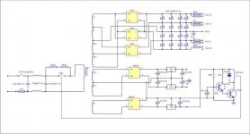
Most big amps have a ±low rail and a ±high rail. The caps on the low rail must be on the outside of the OR-ing diodes, right on the main filter caps (the outputs are connected on the inside of the OR-ing diodes).
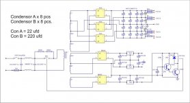
A Crest CA12 uses four 30,000uF (actually eight 15,000uF) in the main supply. The high rails have 22uF electrolytic plus 1.5uF film, the low rails have 220uF electrolytic plus 2.2uF film.
Sometimes you may have to place a small resistor (snubber) in series with the film caps. They may cause oscillations if the grounding scheme is not right. I generally try around 1R, or omit the film caps if I have a problem.
D3, D4 are the OR-ing diodes.
okapi said:makes me want to try building a chip amp powered speaker with the chips mounted right at the driver terminals. i guess most people would suggest an active crossover with this type of set-up but i think i would like to try a passive line level cross over. i would keep the signal digital right up to the speaker.
Keep in mind that a chipAmp is just another kind of opAmp and it cab be used itself as the active component in up to a 3rd order XO.
dave
darian said:So, even keep the crossover in the digital realm and buy a DCX2596 or even two, one per loudspeaker. It's apparently one of the best system you can dream of according to a lot of people!
I just gave one of these back. Stock they sound really bad. Many say (i have no real experience) that they can be made sonically good with expensive mods. Expect to replace a lot of stuff to make it decent.
dave
makes me want to try building a chip amp powered speaker with the chips mounted right at the driver terminals. i guess most people would suggest an active crossover with this type of set-up but i think i would like to try a passive line level cross over. i would keep the signal digital right up to the speaker.
Then you get an active monitor. Many commercial examples available, specially in the pro-audio world.
For example JBL LSP25:
One LM3886 for the tweeter, two bridged LM3886 for the bass/mids.
Keep in mind that a chipAmp is just another kind of opAmp and it cab be used itself as the active component in up to a 3rd order XO.
Or, when you use this speakers for playout from the PC: use a multichannel soundcard, foobar and the foo_dsp_xover plugin.
For free
Franz
planet10 said:
I just gave one of these back. Stock they sound really bad. Many say (i have no real experience) that they can be made sonically good with expensive mods. Expect to replace a lot of stuff to make it decent.
Hi Dave,
Is this your honest evaluation? I just bought one a few months back, but haven't had a chance to use it yet (lack the amps and the speakers are still being painted, again).
Did you give it a fair hearing? Many say that they are fine when set up properly.
MJL21193 said:Is this your honest evaluation? I just bought one a few months back, but haven't had a chance to use it yet (lack the amps and the speakers are still being painted, again).
Did you give it a fair hearing? Many say that they are fine when set up properly.
Yes. Absoultly brilliant for dialing in XO points & topology (be better if they had Mac software, but the front panel is easy enuff to get around), but really hard to listen thru to see how you are doing subjectively. The measuring kit was indispensible in helping out here.
There is an entire DCX2496 modification industry based around this dicotomy... and a huge thread on this forum. This is another piece that has to be considered as a pre-built kit screaming out for mods, or as just another piece of test gear... certainly not worthy of putting into a hifi and listening to in its stock role.
I do plan on getting one of my own but need to budget the time & money for all the mods needed.
dave
planet10 said:
This is another piece that has to be considered as a pre-built kit screaming out for mods, or as just another piece of test gear... certainly not worthy of putting into a hifi and listening to in its stock role.
I do plan on getting one of my own but need to budget the time & money for all the mods needed.
Did you have a modded unit at your disposal to try out for comparison?
I have poked through the mod thread here and visited a few web pages covering various "improvements", but I'm sure some of these are smoke.
There are a few making some money off of this also - I've seen modded units selling for up to $3000! This is ridiculous, IMO.
I did do some testing when I received it to verify that it works properly, and I am very impressed with the results. This is a low noise, low distortion device. When I compare the output of my DIY analog 24db LR filters and how they butcher the waveform to the clean, undistorted waveform that emerges from the DCX, the contest is decided. This on top of bucket loads of functionality.
I'll try mine out for audio eventually, and will probably be completely satisfied with it's operation and sound quality. My ears are not golden after all and I can live with the shame of settling for something that is "not worthy of putting into a hifi and listening to in its stock role".
Hi mhtplsh,
---There is nothing about damping factor improvement as i see.
Kindly clarify.---
A negative resistance scheme does it as it concerns the amplifier output impedance. In fact, the damping factor goes negative. The effect is much more spectacular than any trick aiming at a high damping factor.
About transforms, you are right, strictly speaking, they do not modify the damping factor : they only change the apparent Qec of a driver in a closed box.
sorry a bit long....
just for a moment i would like to revisit the original question......
damping factor is Zl/Zo load impedance divided by output impedance. one simple way to measure it (but it has an error factor proportional to the output impedance) is to put a shorting plug across the input of the amp, and drive the output of the amp with a 10V sine wave fed through a 10 ohm resistor. the resulting voltage measured across the amp output terminals is the residual which is proportional to the output impedance of the amp. since the 10V signal is dropped across a 10 ohm resistor, there is a 1:1 relationship between voltage and impedance, so 1mV=1milliohm. a better method would be to drive the output terminal directly with a 1A AC current source (technically not a "constant current source", but the output current would be 1A rms into the output impedance of the amp). the current source drive would eliminate the error incurred by using a voltage source and resistor. better still, the source could be a triangle wave, so the result would be a linear representation of the output impedance (which in a class AB or class B amp changes nonlinearly around the zero crossing point).
i have been doing some experimenting with output impedance, here's some of what i have found...
output impedance is inversely proportional to a) the open loop gain, and b) the feedback factor
output impedance is proportional to a) the closed loop gain, and b) the open loop output impedance (which is almost completely composed of the resistive losses in the power supply and output stage). in one experiment i had 10 ohm emitter resistors, but still an output impedance of 1 milliohm. probing the gates of the output devices (i used MOSFET outputs because the Rds(on) was easily determined from the data sheet) showed the gates being driven in opposite phase (to the applied signal) about 10V in order to maintain a very small (as close to zero as possible) output condition. keep this in mind...
a speaker is a linear DC motor. if you take a motor (stepper motors are best for this little experiment, though almost any DC motor will do) and turn it by hand you can see a voltage developed by the interaction of the coils and the magnets. the stepper motor will actually produce an AC output, but a DC motor will produce a dc voltage that changes voltage with velocity and changes polarity with direction. this is back EMF. now introduce a short across the winding and try to turn the motor. it's much harder to turn because the back EMF dumps through the short and the resulting current flow sets up magnetic force in the coils which buck the magnets and resist motion. you can do this with a speaker. take a woofer (preferably with a very compliant suspension) and tap on the dust cover with your finger. you will hear it thump and you will feel very little resistance to your impact. now connect a piece of wire between the terminals and thump the speaker again. the cone acts very stiffly, and the sound of the thumps reflects this change. connect the woofer to an amplifier with the power off. you can thump the cone just as if it were open-circuited. turn the power on on the amp with no signal and thump the cone again. it will be as if you had connected a piece of wire across it. this effect from the amplifier is almost completely due to feedback sensing the back emf from the speaker as an error signal and making the amp do whatever it must to correct for it. so in essence an amplifier does exert some control over cone movement. one idea that has been tried, but it's difficult to keep the amp stable in many cases is to take the feedback tap off of the speaker terminals itself in the same way an open frame power supply uses sense wires to provide feedback at point of load for the regulator. this would essentially place the low output impedance directly at the speaker terminals with the amp doing whatever it must to keep the errors at zero.
MJL21193 said:Did you have a modded unit at your disposal to try out for comparison? ...
I did do some testing when I received it to verify that it works properly, and I am very impressed with the results. This is a low noise, low distortion device.
It would have been nice to have a modified unit for comparison, but alas... i did have a good active XO and a couple PLLXOs. In comparison the DCX was as transparent as smoke.
Now with a unit this cheap, with this much functionality, and with Beringer's rep for QC, ir certainly is possible that the unit you have, and the one i had are dissimilar.
dave
- Status
- This old topic is closed. If you want to reopen this topic, contact a moderator using the "Report Post" button.
- Home
- Amplifiers
- Solid State
- Damping factor in DIY amp