Hi
I am trying to find ways of improving the performances and scope of DC servos. In general, their function is very narrow and focused, but I would like to give the servoing amplifier a bigger role.
In summary, I want to combine the accuracy, linearity and high open-loop gain of a precision amplifier with the power and bandwidth of a power amplifier.
Nothing new, and a number of solutions have already been provided.
But I want to implement it in a more general and convenient way, with some additional constraints. The picture shows a (non-working) example of what I try to achieve:
U1 symbolizes the fast, low-accuracy power amp.
U2 is the precision correction amplifier. It compares the output scaled by R4/R5, to the input signal, and corrects the input of U1 via R3.
The HF part of the signal goes directly to U1 via the feedforward capacitor C3.
Obviously, it doesn't work: C2 and C3 introduce two poles in the loop, resulting in a strong gain and phase variation in the middle of the band.
The constraints:
The summing point for LF and HF signals has to be the NI input of the power amp.
The correction amplifier has to be fully isolated from the HF signals, both on the inputs and the output: this is the reason for C2 and C4.
This is also the reason why it is not possible to introduce a lead resistor in series with C3 f.e. The role of U2 must strictly be limited to LF.
Is there a clever way of achieving these objectives, without resorting to ultra-accurate matching, or much more complex circuits?
Attachments
It sounds like you want to build a composite amp. Here's some basics:
http://focus.ti.com/lit/an/sboa002/sboa002.pdf
I've successfully experimented something like this (not intended for high precision):
http://www.diyaudio.com/forums/showthread.php?postid=1528904#post1528904
http://focus.ti.com/lit/an/sboa002/sboa002.pdf
I've successfully experimented something like this (not intended for high precision):
http://www.diyaudio.com/forums/showthread.php?postid=1528904#post1528904
syn08 said:It sounds like you want to build a composite amp.[/url]
Sort of.
But often, like in your example, amplifiers making up the composite have similar frequency characteristics; simple summation techniques can therefore apply.
When the frequency bands have to be separated, and the summation occurs upstream of the main amplifier, things become much more complicated, as I have shown in my example.
This why I chose DC servo as a title, although it's much more radical than usual DC servos.
i used to be the final test and customer service tech for a company that used a DC servo in their power amp the trick was that the servo had a -3db point of 5hz, and was isolated from the audio feedback loop. it worked extremely well (so well, in fact, that in doing the DC offset adjustment, if you forgot to disconnect the servo, adjusting the offset pot did absolutely nothing except change the mix of even harmonics in the distortion residual).
your picture is missing most vertical lines, but i think i get the idea of what you're trying to do. you have the input to the servo tapping off from part of the audio feedback, and the lack of isolation between your AC and DC feedback loops is where your problem lies. i'll upload a copy of a servo i know works later, and you'll see what i mean.
your picture is missing most vertical lines, but i think i get the idea of what you're trying to do. you have the input to the servo tapping off from part of the audio feedback, and the lack of isolation between your AC and DC feedback loops is where your problem lies. i'll upload a copy of a servo i know works later, and you'll see what i mean.
This is not specifically intended for audio amplifiers, it is more general, applicable to instruments amplifiers f.e., but it could also benefit audio amplifiers:lineup said:i do not use dc servos
and probably never will
the normal dc feedback is enough for my amplifiers
but not for some others amps, i suppose
regards
lineup
If the correction amplifier is one of the new, ultra-low distortion chips, it will contribute to the linearization of the lower part of the spectrum, which can be beneficial.
Use the "maximize" tool or handle of your browser.your picture is missing most vertical lines, b
It is easier to get high bandwidth low noise low distortion amp closing a GFB loop around stages with local feedback than the same loop around the same stages without local feedbacks. I once made an amp in class A+C with such approach, it was much better than any traditional AB class amp, both sonically and according to measurements. 3 negative feedbacks on AC, and one global on AC and DC.

Elvee said:Hi
I am trying to find ways of improving the performances and scope of DC servos. In general, their function is very narrow and focused, but I would like to give the servoing amplifier a bigger role.
In summary, I want to combine the accuracy, linearity and high open-loop gain of a precision amplifier with the power and bandwidth of a power amplifier.
Nothing new, and a number of solutions have already been provided.
But I want to implement it in a more general and convenient way, with some additional constraints. The picture shows a (non-working) example of what I try to achieve:
U1 symbolizes the fast, low-accuracy power amp.
U2 is the precision correction amplifier. It compares the output scaled by R4/R5, to the input signal, and corrects the input of U1 via R3.
The HF part of the signal goes directly to U1 via the feedforward capacitor C3.
Obviously, it doesn't work: C2 and C3 introduce two poles in the loop, resulting in a strong gain and phase variation in the middle of the band.
The constraints:
The summing point for LF and HF signals has to be the NI input of the power amp.
The correction amplifier has to be fully isolated from the HF signals, both on the inputs and the output: this is the reason for C2 and C4.
This is also the reason why it is not possible to introduce a lead resistor in series with C3 f.e. The role of U2 must strictly be limited to LF.
Is there a clever way of achieving these objectives, without resorting to ultra-accurate matching, or much more complex circuits?
Look up some old CRO service manuals. This is along the lines of how wide bandwidth, DC-coupled oscilloscope input amplifiers used to be made when IC opamps started to come into fashion.
The the HF response of the opamp was deliberately rolled off at a transition frequency of at some kHz. The directly coupled output of the opamp was then summed with the output of a discrete, AC coupled amplifier for the higher frequencies, coming in with a comlementary high-pass response at the transition frequency for an overall summed flat response.
I once copied the idea for a precision instrumentation thingle using an AD707 and a GHz fT discrete transistor array for the AC ampifier (can't remember the part # for the latter, but Farnell sells it).
Cheers,
Glen
Re: Re: Improving DC-servos
I have seen such circuits. But the LF and HF signals simply follow parallel paths, and are summed at or near the output. This eliminates the closed loop difficulties.G.Kleinschmidt said:
Look up some old CRO service manuals. This is along the lines of how wide bandwidth, DC-coupled oscilloscope input amplifiers used to be made when IC opamps started to come into fashion.
The the HF response of the opamp was deliberately rolled off at a transition frequency of at some kHz. The directly coupled output of the opamp was then summed with the output of a discrete, AC coupled amplifier for the higher frequencies, coming in with a comlementary high-pass response at the transition frequency for an overall summed flat response.
I once copied the idea for a precision instrumentation thingle using an AD707 and a GHz fT discrete transistor array for the AC ampifier (can't remember the part # for the latter, but Farnell sells it).
Cheers,
Glen
Re: Re: Re: Improving DC-servos
Well yeah, that's pretty much the idea. With a little component matching it is a relatively simple way to a uV-precision DC coupled amplifier, -3dB at several hundred MHz.
Cheers,
Glen
Elvee said:This eliminates the closed loop difficulties.
Well yeah, that's pretty much the idea. With a little component matching it is a relatively simple way to a uV-precision DC coupled amplifier, -3dB at several hundred MHz.
Cheers,
Glen
ok.... finally got time to do this on the computer that has the image i was looking for......
the DC servo from the APT-1 amp. one of the best servo designs i've seen.
the line "to diff -" connects directly to the inverting input of the power amp, the line "to amp output" connects directly to the amp output, and the "to jfet switch" goes to a jfet that discharges the 100uf cap when the power is shut off. the "to DC pot" line goes to the wiper of a dc offset pot that has a range of +/- 0.7V.
Attachments
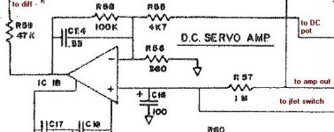
the DC feedback path is isolated from the AC feedback path by R57, which isolates it from the feedback tap of the output stage through a 1 Meg resistor, and R59, which isolates the AC feedback on the diff- node from the op amp output (a low impedance node) through the 47k resistance
lineup said:i do not use dc servos
and probably never will
the normal dc feedback is enough for my amplifiers
Nelson Pass said:Servos just aren't elegant. I much prefer to make the circuit
behave itself in the first place. Sometimes that's not practical.
Servos are often justified by the benefits of removal of a cap
from the main feedback loop, but we are just substituting it
with another (ok, probably better) cap and an active circuit.
I personally think that there are bigger devils out there than the
lowly, much maligned capacitor. Any active gain device or
transformer is a much bigger offender, and deserves more
attention than wire or capacitors.
.
As I, Lineup, already said:
why bother with those dc-servos? if there are satisfactory other ways.
Nelson said:
Servos just aren't elegant.
I much prefer to make the circuit behave itself in the first place.
Some times Nelson Pass gives a glimt of his reasoning behind.
And it is plain logic, people.
Mixed with a very great portion of experience in audio thinking

At times Lineup find him self coming to same design conclusions as Real Masters of Audio Amplifiers.
Only it will happen in parallel, many years later
Like in these many nice design ideas for good audio circuits
by Lineup Diy Audio LAB
Servos are often justified
by the benefits of removal of a cap from the main feedback loop,
but we are just substituting it
with another cap and an active circuit.
The experts in the DIY headphone amp forums say that they can hear a loss in dynamics when a servo is summed into a diffamp input. My ears agree on this loss of dynamics with 98 db/watt speakers.
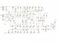
Any experience with DC servos that adjust bias currents instead of summing into an input? I'm especially interested in "SuperSymm" topologies where there are both + and - output drivers. My current amp uses an opamp with integrator capacitors in feedback loops on both the + and - opamp inputs, driven from the + / - outputs. This amp topology is supersymm with both positive and negative symmetrical input JFET diff pairs driving +/- output circuits. The servo opamp drives (overpowers by summing into) the cascode voltage bias circuit that goes to both positive and negative halves.
I've cut one such bias adjustment servo from a member's posted amp, which used descrite transistors instead of opamps.
Attachments
your circuit as shown is
1> redundant, you are inserting what's supposed to be a DC servo, when you have C1 in circuit. C1 already does your DC correction without the servo.
2>has a summed input with too much emphasis on the servo. C3 is too small a value, 1uf would present a lot lower reactance and the 47k resistor would present much better isolation of the DC feedback loop
3>has too much positive feedback. i don't know why you put R6 there, but your servo is in danger of becoming an oscillator.
4> has marginal isolation from the AC feedback loop. increase the value of R4 by at least a factor of 10
5> the servo has no DC reference. eliminate C4 and tie the noninverting input to ground
this is probably closer to answering your original question, than the ensuing debate about whether servos are worth the effort.
My last project is a symmetrical double diff amp driving two, bridged output stages that use two servos, one for each side. Each "servo" consists of a simple single ended amplifier from a +/-15V source (circuit had to be made discrete ), with a lower output Z, the output acts as a virtual gnd reference for each input. Input Z looking in from the audio source is higher. The input differentials (J-fets) each have a floating DC reference connected to the source node, just a voltage divider from +V to -V of proper impedance. Without this, the common mode would not have reference to 0V. Even though the speaker doesn’t connect to gnd, it is important for balanced operation that each output be 0VDC. The difference about this circuit is that the GNFB loop is only to sense the output DC. Each gain stage has its own local feedback and is cascade to the next. Just something a bit different.
Sy makes a good point that the pole Fc must be low so it doesn't amplify any audio signal. In my circuit, the servo pole is ~1.3Hz and the input high pass Fc ~15Hz. Trial and error to fine tune for best stability and sonics. I found out in this case that the input needs limiting to prevent hard clipping. Hard clipping creates a DC component at the outputs and tends to throw the servos into slight oscillations at ~1 or 2 cycles. That's my story, but yours is probably different.
), with a lower output Z, the output acts as a virtual gnd reference for each input. Input Z looking in from the audio source is higher. The input differentials (J-fets) each have a floating DC reference connected to the source node, just a voltage divider from +V to -V of proper impedance. Without this, the common mode would not have reference to 0V. Even though the speaker doesn’t connect to gnd, it is important for balanced operation that each output be 0VDC. The difference about this circuit is that the GNFB loop is only to sense the output DC. Each gain stage has its own local feedback and is cascade to the next. Just something a bit different. Sy makes a good point that the pole Fc must be low so it doesn't amplify any audio signal. In my circuit, the servo pole is ~1.3Hz and the input high pass Fc ~15Hz. Trial and error to fine tune for best stability and sonics. I found out in this case that the input needs limiting to prevent hard clipping. Hard clipping creates a DC component at the outputs and tends to throw the servos into slight oscillations at ~1 or 2 cycles. That's my story, but yours is probably different.
U1 is a low-accuracy, fast amplifier. C1 avoids the multiplication of its offset voltage by the amplifier gain.unclejed613 said:your circuit as shown is
1> redundant, you are inserting what's supposed to be a DC servo, when you have C1 in circuit. C1 already does your DC correction without the servo.
Anyway, C1 has a rather beneficial effect seen from the servo loop perspective, as it provides some lead compensation.
There is matter for some discussion. As I have said, I would like to use the correction (let's not call it servo, as it seems confusing) amplifier to linearize the low-frequency response. Now how low is low depends on the specific amplifier, taste, etc.2>has a summed input with too much emphasis on the servo. C3 is too small a value, 1uf would present a lot lower reactance and the 47k resistor would present much better isolation of the DC feedback loop
Again, it is in the optic of a correcting amplifier: at low frequencies, U2 compares the input via R6, to the output via R4/R5 (identical to R1/R2), and drives U1 to remove any error.3>has too much positive feedback. i don't know why you put R6 there, but your servo is in danger of becoming an oscillator.
The circuit is meant to illustrate the concept (and the problems arising thereof). Actual values could easily be adapted, but the fundamental, theoretical issues have to be addressed first.4> has marginal isolation from the AC feedback loop. increase the value of R4 by at least a factor of 10
See point 3.5> the servo has no DC reference. eliminate C4 and tie the noninverting input to ground
It is indeed.this is probably closer to answering your original question, than the ensuing debate about whether servos are worth the effort.
Quite true, but I want to use the loop gain of the servo (=correction) amplifier at low frequencies, which means I cannot hide the loop stability problems under the carpet, by splitting the poles f.e.Nearly all audible issues with a servo can be removed by two expedients: setting its pole low enough and putting a passive RC pole tuned a decade or more higher at the output.
if you're using the servo to reduce distortion between 20 hz and 1khz, again it's somewhat redundant. that's where most diff amps excel, since they have so much open loop gain. what's causong you problems here is you have an amplifier in both your AC and DC feedback loops, with gain, and it's on the verge of becoming an oscillator (hence your strange behavior at 1khz). the feedback is contensing with your input stage for control of the overall system, and making it unstable
- Status
- This old topic is closed. If you want to reopen this topic, contact a moderator using the "Report Post" button.
- Home
- Amplifiers
- Solid State
- Improving DC-servos