Hello
I need help building a CCS to power 1-24 Led's which will be used to show the position of my volume pot.
using two pnp transitors has been mentioned but i'm not sure how this works or how to implement it!
Any help would be appreciated.
these are the led's i will probably use: Hyper blue diffused led's
There's a few different ways, Google and 10 minutes will show you...
Although I don't think you need a CCS, you need a bargraph driving chip or bunch of comparators. Otherwise how are you going to make them come on in sequence? Also you need a 3 or more gang pot (2 tracks for left & right, 1 for the LEDs) if you are trying to do this all analogue.
Although I don't think you need a CCS, you need a bargraph driving chip or bunch of comparators. Otherwise how are you going to make them come on in sequence? Also you need a 3 or more gang pot (2 tracks for left & right, 1 for the LEDs) if you are trying to do this all analogue.
the problem we fact here is
that if
you feed the transistor that will trigger LED to light
at one certain position
from the audio signal = the stepped attenuator resistor divider
then you will have
1. one construction design problem
2. possibly some distortion caused by the current needed to trigger the transistor BASE
solution can be.
use one 2 x 24 position stepped attenuator
where one set of those 24 positions are NOT for SIGNAL
but only for trigger one of 24 transistors
But really,
i would not go for any LEDs to show volume level
just use one normal scale with one mark for each position
as you turn the knob
this way, you can use your 2x24 stepped attenuator
for BOTH left and RIGHT channel
Can you tell a bit more about what gear you have, so far.
Regards
Lineup
here goes
Ok I want to achieve a volume indicator using blue Led's, the first step will iluminate the first led the second will illuminate the first and second and so on until all are lit.
I intend to use a two channel 24 way stepped attenuator for left right signals which i was planning to incorparate into the amp anyway.
Then I plan on making my own pcb with a 24 way switch incorparated, this will be mounted on the rear of the front panel on the same shaft as the attenuator this will feed the power to the led's the wiper will be connected to the supply. the Led's will be wired in series so i can switch between the led's lighting them in sequence. hopefully
My problem is with the supply and values of said supply. now i know there are easier ways of doing this but where would be the fun in that...lol
I have been doing some research on the net to try and teach myself but i'm not getting very far! my trouble is I learn by doing something so if you could help me i will grasp it as im doing it.
If that makes sense.
Matt
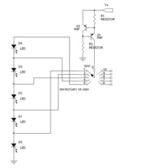
Neat idea but it's going to need a supply voltage of 24x Vf yielding 74.4 volts even before the CCS headroom is taken into account. Also maybe the knob will be a bit stiff with two lots of switches on it?
Anyway I have a good little circuit for you here.
R3 is the load i.e. your string of LEDs. As shown with LEDs having Vf=2.1 used for the CCS it's running at 5mA. If you use your blue LEDs having different Vf then you will need to change the 560 ohm resistors R1 and R2. The transistors shown will be fine for the application but small heatsinks are needed. The supply voltage should be 82-100 volts.
Anyway I have a good little circuit for you here.
An externally hosted image should be here but it was not working when we last tested it.
R3 is the load i.e. your string of LEDs. As shown with LEDs having Vf=2.1 used for the CCS it's running at 5mA. If you use your blue LEDs having different Vf then you will need to change the 560 ohm resistors R1 and R2. The transistors shown will be fine for the application but small heatsinks are needed. The supply voltage should be 82-100 volts.
Hi Matt
Is your intent to indicate the level of gain or the level of signal? If you are trying to show the signal level, a LM3915 may be a simple solution. This chip uses a logrithmic scale. The LM3914 is a the linear version. IMO, easier than building a discrete version and they can be strung together for more led's.
Is your intent to indicate the level of gain or the level of signal? If you are trying to show the signal level, a LM3915 may be a simple solution.
This chip uses a logrithmic scale. The LM3914 is a the linear version. IMO, easier than building a discrete version and they can be strung together for more led's.CBS240 said:
Is your intent to indicate the level of gain or the level of signal? If you are trying to show the signal level, a
it is mainly a visual thing just to show which position of the attenuator.
richie00boy
That does look good, what is the purpose of the led's in the ccs?? Iwas thinking along very similar lines but no led's.. what do you think of this?
a very simple idea will be
to forget using all these complicated stuff and simply make a mechanical construction or any other way to run parallel with your volume control another pot
in case your volume control will be a step switch then simply you need to have a step switch with one partition more (one partition to be used as volume control and then another one to be used as the led control)
then you can use LM3914 or uaa 2022 or any other led driver but hooked up as a volt meter ..... so in step number one you have voltage enough to drive the first led and then 10 turn trimmers or very good calculations and presision resistors to go to next step and so on and on till the last step .....
the same will apply if you have a potentiometer but there calibrating the led potentiometer to follow the volume will be not an easy task
regards sakis
thats good,
so the 1M resistor needs to go where? inbetween the transistors is that correct?
What value resistors do you think at R1 and R2 for 3.1vf??
this is stupid but the supply will not fry the first few led's will it.....it will increase V according to demand from the LED's..is that correct?? or am i getting it the wrong way round??
richie00boy said:That's the entire point of current source drive, lol that's what you asked for anyway.
Use ohm's law to work it out for different Vf
I know i know...being new and still learning i'm constantly not sure if what i'm doing is correct...lol Re the resistors, no free lunch aye..lol
matt
I'll run through it as you might get caught out with a couple of things.
We know the CCS is running at 5mA so that gives 2.5mA in the LED and 2.5mA in the resistor. We can see using the values I have above that the voltage across the resistor is 0.0025A * 560R = 1.4V, then there is the Vbe to take into account, 2.1 - 1.4 = 0.7 with the transistors shown.
So now with LEDs of Vf = 3.1V let's see what happens. Resistor voltage will be 3.1 - 0.7 = 2.4. We want 2.5mA in the resistor so that means we need 2.4V / 0.0025A = 960 ohms.
Vf is quoted at 2.1V (or 3.1V for your LEDs), but this figure does vary a bit with current and is usually stated at full current which you won't want to run at. So some tweaking may be necessary, but it's probably close enough for what you want.
richie00boy said:Neat idea but it's going to need a supply voltage of 24x Vf yielding 74.4 volts even before the CCS headroom is taken into account. Also maybe the knob will be a bit stiff with two lots of switches on it?
Anyway I have a good little circuit for you here.
An externally hosted image should be here but it was not working when we last tested it.
R3 is the load i.e. your string of LEDs. As shown with LEDs having Vf=2.1 used for the CCS it's running at 5mA. If you use your blue LEDs having different Vf then you will need to change the 560 ohm resistors R1 and R2. The transistors shown will be fine for the application but small heatsinks are needed. The supply voltage should be 82-100 volts.
With good transistors used it will never start, so you need one more resistor to provide some initial current.
sawreyrw said:Wavebourn,
onform told us that in post #11.
Oops... I did not read all posts carefully. Anyway, a reminder would not be odd.
thats good..
Thanks a lot that answers a few Q i was about to ask...lol just designing the pcb for the switch and supply at the mo,
This all operates outside of the amp cicuit and has it's own supply I will probably sheild the supplies from the main amp board anyway but thanks for the comment it will be interesting to see if it does affect anything. a simple swith can be addded later if it does.
I will probably try it without first but add in the provision for it when printing the boards..again we shall see...
thanks guys...
richie00boy said:I'll run through it as you might get caught out with a couple of things. .
Thanks a lot that answers a few Q i was about to ask...lol just designing the pcb for the switch and supply at the mo,
rocco gibralter said:Dont want to sound snobby, But LED's mess up the sound making it grainy, I'd fit a switch to turn them all off when your listening to music........
But dont let me sway you!
This all operates outside of the amp cicuit and has it's own supply I will probably sheild the supplies from the main amp board anyway but thanks for the comment it will be interesting to see if it does affect anything. a simple swith can be addded later if it does.
Wavebourn said:
With good transistors used it will never start, so you need one more resistor to provide some initial current.
I will probably try it without first but add in the provision for it when printing the boards..again we shall see...
thanks guys...
- Status
- This old topic is closed. If you want to reopen this topic, contact a moderator using the "Report Post" button.
- Home
- Amplifiers
- Solid State
- can anyone help with CCS