i am sure this is not your friend's design. the PCB is sold commercially by a member here, why bother to erase the owner's website on the schematic?. if there is any errors, please do share and i am sure the seller would be interested to know.
oh btw, his nick here is kristijan-k.
oh btw, his nick here is kristijan-k.
More specific, Mr.Pass design it would be (omg I'm Yoda )
)
Anyway, here's link on Kristian's page... so there's no need to be mysterious about schematics or designer....")
http://www.kk-pcb.com/vpzen.html
)Anyway, here's link on Kristian's page... so there's no need to be mysterious about schematics or designer....
http://www.kk-pcb.com/vpzen.html
To me' if using the tubes like that. I'd rather do a mu-follower with a mosfet on the anode and a simple follower stage with mosfets. Or just go with a ZEN-X for example :-D..
or search the internet for other hybrid designs, there are some interresting out there.. :-D one with lundahl transformers connected to the gates, I wonder how good that one works,looks cool and really minimalistic though..
or search the internet for other hybrid designs, there are some interresting out there.. :-D one with lundahl transformers connected to the gates, I wonder how good that one works,looks cool and really minimalistic though..
and here is the pcb board components lay outsith said:Anyway, here's link on Kristian's page... so there's no need to be mysterious about schematics or designer....
http://www.kk-pcb.com/vpzen.html
with 1 tube + mosfets
An externally hosted image should be here but it was not working when we last tested it.
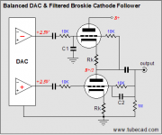
Matthewong said:I not really understand why got 2 connection to the grid for the e88cc tube.
so what is so wrong about the balanced inputs at the tube stage? u have to elaborate if u ask for help.
commstech said:
so what is so wrong about the balanced inputs at the tube stage? u have to elaborate if u ask for help.
What I trying to ask is how should I connect the both connection to the tube's grid since only available one grid per tube. Please refer to the following diagram.
Attachments
Depends what source you have.
A) Balanced source. With XLR connector. From some professional microphones etc.
With this source you simply connect the 3 wires to correspoding 3 input poles.
You can of course reverse + and -
This will change the phase, the polarity of the output from MOSFET.
B) Normal RCA Phono source. This has got 2 poles: + and GND
Here you have 2 options.
1. Connect to Tube + and GND.
2. Connect to Tube - and GND.
Using B2, the reverse connection.
Will keep the phase, polarity of signal from MOSFET Out.
Because the MOSFET stage reverses the polarity of signal.
The MOSFET output stage looks like something by Nelson Pass
with his usual local negative feedback around the lower IRFP240
Matthewong said:So that's mean the both connection from the GRID is connected together in the pin 2 or pin 7, usually GRID will be placed in pin 2 for 1st stage or pin 7 for second stage.
The schematic is drawn with two connections to each grid, only to make it easier to draw from left to right. Electrically it's the same as showing a single connection. The 47k feedback resistors connect to each grid at the same terminal as the 33k input resistor.
- Status
- This old topic is closed. If you want to reopen this topic, contact a moderator using the "Report Post" button.
- Home
- Amplifiers
- Solid State
- Tube-Mosfet Single-Ended Amplifier!