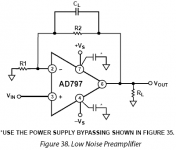
Don't worry too much about matching impedance, BUT keep R1 LOW! 10 ohms is best here, but 30 ohms or so isn't too bad.
Remember, you don't necessarily want to measure 1/f noise below 100 Hz, so you might still use a cap in series with R1 to remove ultra low frequency noise, that will just make your meter flutter. Second, you should put an input resistor on the positive input that connects to ground. This is just good practice. 50K-100K should be OK. It will NOT add any extra noise as it is in PARALLEL, and not in series with the input as long as the source being measured is of low value in output impedance. Third you should keep the 1500pf or so across the main feedback cap, to reduce the bandwidth, or else you will just measure the ultrasonic stuff.
Remember, you don't necessarily want to measure 1/f noise below 100 Hz, so you might still use a cap in series with R1 to remove ultra low frequency noise, that will just make your meter flutter. Second, you should put an input resistor on the positive input that connects to ground. This is just good practice. 50K-100K should be OK. It will NOT add any extra noise as it is in PARALLEL, and not in series with the input as long as the source being measured is of low value in output impedance. Third you should keep the 1500pf or so across the main feedback cap, to reduce the bandwidth, or else you will just measure the ultrasonic stuff.
jackinnj said:In case you were wondering:
* BF862 SPICE MODEL MARCH 2007 NXP SEMICONDUCTORS
* ENVELOPE SOT23
* JBF862: 1, Drain, 2,Gate, 3,Source
Thanks, I'll see how this looks. My actual measurements were very optimistic on 1/f noise. Good duals are very hard to find these days and I wanted to show something in the ballpark of $1-2 in parts. The op-amps are not critical except the headroom issues on the one that sops up the common mode signal.
Hi!
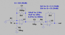
I have something like this in my mind (PSU bypassing omitted).
First opamp (AD797, LT1028) is gain of 330 w/ low pass filter. I've added second stage so that I could easily make an high pass filter.
For second stage there is no need for an low noise opamp.
I am going to use rotary switches to switch between different LP/gains.
This simple circuit should work nicely. I hope I haven't miss anything.
Thanks for all the tips")
Cheers,
Matej
I have something like this in my mind (PSU bypassing omitted).
First opamp (AD797, LT1028) is gain of 330 w/ low pass filter. I've added second stage so that I could easily make an high pass filter.
For second stage there is no need for an low noise opamp.
I am going to use rotary switches to switch between different LP/gains.
This simple circuit should work nicely. I hope I haven't miss anything.
Thanks for all the tips
Cheers,
Matej
Attachments
Measuring 1/F noise
I have an HP35670 -- but can't find the software anywhere -- at any rate here is a nice, jointly authored article on measuring 1/f noise.
http://www.elanix.com/pdf/1overf_Noise.pdf
I have an HP35670 -- but can't find the software anywhere -- at any rate here is a nice, jointly authored article on measuring 1/f noise.
http://www.elanix.com/pdf/1overf_Noise.pdf
MateJS, you are close, but it might be useful to put a series electrolytic cap in series with R1, maybe 1000 uf, but it not be too large, because it can have a very low voltage rating. This will help the potential offset, and remove any extreme 1/f from the test. Extreme gain may not be useful, because you will still have a measurable noise floor, due to still having a relatively wide bandwidth. Scott is also right about the 1meg. Only fet input stages can get away with that easily. 50K should be OK. This is what I use with the AD797(s) in my Sound Tech analyzer.
Re: Measuring 1/F noise
I once went down to 11 micro-Hz with one of those characterizing current noise.
jackinnj said:I have an HP35670 -- but can't find the software anywhere -- at any rate here is a nice, jointly authored article on measuring 1/f noise.
http://www.elanix.com/pdf/1overf_Noise.pdf
I once went down to 11 micro-Hz with one of those characterizing current noise.
Re: Re: Measuring 1/F noise
At 11uHz can't you just see the little critter comin' and whack it with a shovel?
scott wurcer said:
I once went down to 11 micro-Hz with one of those characterizing current noise.
At 11uHz can't you just see the little critter comin' and whack it with a shovel?
For maximum versatility you could use an instrumentation amplifier. There are many already available or you could build this little circuit. The FET's need to be matched or you need a big AC coupling cap in series with the gain resistor which goes between the sources of the input FET's.
I wonder if you've given more thought to that circuit (post 17) after writing up the two-part Linear Audio articles on microphone preamplifiers. I've built a couple versions with both BF862 and K170 and an LME49720 opamp.
I recommend the transistor matching device you showed in the LA article.
- Status
- This old topic is closed. If you want to reopen this topic, contact a moderator using the "Report Post" button.
- Home
- Amplifiers
- Solid State
- Measuring low noise