Even better I found circuit diagrams...
http://www.altronics.com.au/download/ndb/circuits/a/A4170 04-07-05.PDF
http://www.altronics.com.au/download/ndb/circuits/a/A4170 04-07-05.PDF
Class H usually has at least 2 sets of Power supply rails. Your schematic shows +/-63V rails. Class H would typically have rails also at twice that voltage +/- 126V with a step system between the rails that would swing the amp up to the higher rail on strong signal demands that would otherwise exceed the lower rail voltage.
QSC's schematics are one example of this. there available online to look at.
Class G i don't know much about???
QSC's schematics are one example of this. there available online to look at.
Class G i don't know much about???
Hi guys,
I'm not an amp building fella, more of a speaker building chump, so I wasn't sure. Thanks for the clarification.
Is there anything else interesting that you can tell from the schematic? Any potential for mods to improve performance?
It's rated at 400W x 2 into 8 ohms, 600 into 4 ohms.
I will try and post some pictures tonight.
It's designed as a PA amp so have cooling fans.
many thanks,
Thanh.
Internals-
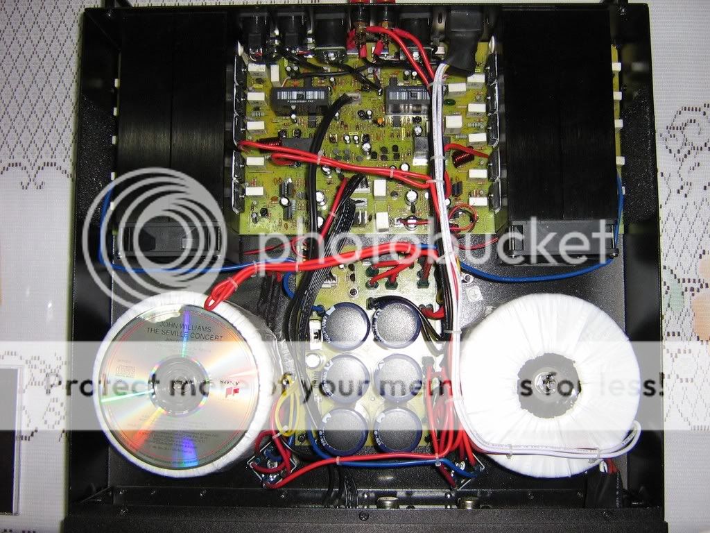
Toroidal transformers- 5.5" diameter, 2.5" high. CD inserted for scale.
Fan forced heatsinks, 5 pairs of transistors per channel.
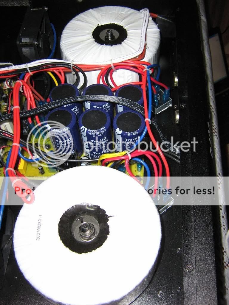
6,800uF 100V capacitors, 6 in total.
I'm starting to doubt the 400W per channel rating.
Surely you would need bigger transformers than that?
regards,
Thanh.
Toroidal transformers- 5.5" diameter, 2.5" high. CD inserted for scale.
An externally hosted image should be here but it was not working when we last tested it.
Fan forced heatsinks, 5 pairs of transistors per channel.
6,800uF 100V capacitors, 6 in total.
I'm starting to doubt the 400W per channel rating.
Surely you would need bigger transformers than that?
regards,
Thanh.
Thanks. Maybe I should have retitled this thread
Debunking Unknown Brand Amplifiers with Ambiguous Specifications.
")
Thanks for the enlightment. This is a DIY audio website after all, and I'm trying to learn. Is there a quick and dirty way to calculate power output given a rail voltage of +/- X Volts?
This is not my own amp, so I'm not afraid of hearing honest feedback.
I've been using it to power my woofer system, and it was beyond reproach.
For full range use however, I don't have a verdict yet.
regards,
Thanh.
Debunking Unknown Brand Amplifiers with Ambiguous Specifications.
Thanks for the enlightment. This is a DIY audio website after all, and I'm trying to learn. Is there a quick and dirty way to calculate power output given a rail voltage of +/- X Volts?
This is not my own amp, so I'm not afraid of hearing honest feedback.
I've been using it to power my woofer system, and it was beyond reproach.
For full range use however, I don't have a verdict yet.
regards,
Thanh.
After carefully reviewing the specs, the rated ouput was-
"TA 1KHz THD 0.1%"
After reading
http://www.rocketroberts.com/techart/powerart_a.htm
I suspect that rating is peak power.
So this amp is good for around 200W continuous into 8 ohms, which seems more realistic given that the toroids at probably around 500-600VA each...
Now to install some silent fans...
Can anything be done about the switching out the NE5532 opamps?
It's very generous on the output devices for even the full advertised power. Certainly minimum of 500W per channel based on that alone. Although the power supply does not really look up to that level of power.
Rail voltage minus say 10V for losses will give you the peak swing.
Power = (volts x volts) / load impedance
Then half this result to get RMS power.
Rail voltage minus say 10V for losses will give you the peak swing.
Power = (volts x volts) / load impedance
Then half this result to get RMS power.
"Can anything be done about the switching out the NE5532 opamps?"
The 5532 isn't that bad, I would leave them alone.
All those polarized electrolytic caps in the signal path (including the feedback loop) are causing far more signal degradation.
Sheet 4 of the schematic shows a ±150V high current supply that doesn't look like it applies to this amplifier.
The 5532 isn't that bad, I would leave them alone.
All those polarized electrolytic caps in the signal path (including the feedback loop) are causing far more signal degradation.
Sheet 4 of the schematic shows a ±150V high current supply that doesn't look like it applies to this amplifier.
FLASH !
That's not the correct schematic, here is the correct schematic:
http://www.altronics.com.au/download/ndb/circuits/a/A4170.PDF
With ±97V it is 400W/8R, 600W/4R, although 5 plastic output pairs in class AB is totally inadequate for 4R.
That's not the correct schematic, here is the correct schematic:
http://www.altronics.com.au/download/ndb/circuits/a/A4170.PDF
With ±97V it is 400W/8R, 600W/4R, although 5 plastic output pairs in class AB is totally inadequate for 4R.
Hmmm.
The heatsinks are fan forced, so maybe the size is adequate?
I could change the electrolytics to polyprop, but that would have to wait for another weekend (or month).
Ok so there are 2 schematics, both for the same apparent "A4170" or "Q400" unit.
The first posted I posted has a mix of pages dated 2007 & 2005.
The 2nd one linked by DJK is dated 2003.
Things get murky now because I have no idea which one is correct.

- Status
- This old topic is closed. If you want to reopen this topic, contact a moderator using the "Report Post" button.
- Home
- Amplifiers
- Solid State
- How to determine if class G/H?