At the first startup my amplifier speaker output measurement give 0,2VDC (between speaker + and -), which slowly decrease to zero and then few millivolts to minus side (-0,03V).
 Question(1) Is this normal manner? Elektor magazine instructions says that normal offset is 0,1V or less.
I measure also quiescent current by measuring voltage between test points tp1 and tp3 and I get about 0,1VDC when trimpot was set to fully left (counter clockwise). Elektor magazine instructions says that recommed voltage is between 0,044V and 0,055V, so I have double. When I turn little bit trimpot to right then voltage rise little bit too, so I turn it back to left.
When amplifier was switched on about one minute then heatsink get quite warm but not hot.
In RCA input I have one 220ohm resistor to prevent any oscillation in input, but I don't know do that give any effect.
I have little differencies in my schematic too. In amplifier part those T7 and T9 should be BC550C and BC560C, but I have BC550B and BC560B because local shop don't have those C -models.
Question(2) Have I misunderstand that letter after numbers, is that current amplification factor (hfe)?
Question(3) Will this cause this strange behaviour?
Also those D1 and D2 (leds) should be red, but I have green.
Quoestion(4) Can this cause this strangeness, because I remember that different color leds have different threshold voltage?
Also in protection circuit that offset compensation circuit should have opamp OP77, but I have OP07. In OP77 datasheet have been written that OP77 is replacement for OP07. I use that OP07, because local shop don't have those OP77 models.
Quoestion(xxx) What should I do next??? Is there some page or have some one Cresendo owner measured any currect and voltage values from different points in circuit, so that I can compare those values mine ones.
Any "operation smoke" have not seen, but is that possible that I have already burnt some components, because I get so much quiescent current?
(No protection circuit schematic included yet)
Question(1) Is this normal manner? Elektor magazine instructions says that normal offset is 0,1V or less.I measure also quiescent current by measuring voltage between test points tp1 and tp3 and I get about 0,1VDC when trimpot was set to fully left (counter clockwise). Elektor magazine instructions says that recommed voltage is between 0,044V and 0,055V, so I have double. When I turn little bit trimpot to right then voltage rise little bit too, so I turn it back to left.
When amplifier was switched on about one minute then heatsink get quite warm but not hot.
In RCA input I have one 220ohm resistor to prevent any oscillation in input, but I don't know do that give any effect.
I have little differencies in my schematic too. In amplifier part those T7 and T9 should be BC550C and BC560C, but I have BC550B and BC560B because local shop don't have those C -models.
Question(2) Have I misunderstand that letter after numbers, is that current amplification factor (hfe)? Question(3) Will this cause this strange behaviour?Also those D1 and D2 (leds) should be red, but I have green.
Quoestion(4) Can this cause this strangeness, because I remember that different color leds have different threshold voltage?Also in protection circuit that offset compensation circuit should have opamp OP77, but I have OP07. In OP77 datasheet have been written that OP77 is replacement for OP07. I use that OP07, because local shop don't have those OP77 models.
Quoestion(xxx) What should I do next??? Is there some page or have some one Cresendo owner measured any currect and voltage values from different points in circuit, so that I can compare those values mine ones.Any "operation smoke" have not seen, but is that possible that I have already burnt some components, because I get so much quiescent current?
(No protection circuit schematic included yet)
Attachments
Hi Eccu,
as I assembled the crescendo myself and had problems likewise I wrote to Elektor to get some measurements from them.
Have a look here : http://www.diyaudio.com/forums/showthread.php?threadid=10606&highlight=new+adventures
On the second page is the mail from Elektor.
I´m no expert but it really might be the choice of components as your quiescent current is definitely too high at the lowest setting.
Did you thermally couple input differential pair and LED/transistor?
I´d definitely put red LED´s in and BC5X0C transistors as it isn´t a cost factor.
Hope you didn´t buy the wrong Z-diodes, just like me ;-)
Regards+Good luck
Jens
Hi joensd...
How is going?
Yes, I have thermally coupled those LEDs and transistors.
Local dealer does not have rectancular red LEDs, only green, so I must order those from different place.
I must test other channel today and if that act same way, then I must buy those BC5*0C transistors.
Do any substitute transistors exist (BC550C and BC560C)?
Eccu said:
Do any substitute transistors exist (BC550C and BC560C)?
BC549C and BC559C should do fine. Even B types, which maybe easier to find, would do the job well.
Carlos
That's fine, the slow decrease to -0.03V is caused by the offset compensation circuit. (So at least that's working properlyEccu said:At the first startup my amplifier speaker output measurement give 0,2VDC (between speaker + and -), which slowly decrease to zero and then few millivolts to minus side (-0,03V).
The threshold voltage of the LED determines (with R17/R20) the current setting for the current source around T5. Usually (IIRC) a green LED has a higher threshold voltage than a red LED -> higher current. This could cause the other problem you describe: not being able to reduce the bias enough (only down to 0.1V between tp1 & tp3, which is about 450mA).
Also those D1 and D2 (leds) should be red, but I have green.
Instead of getting a red LED you could also adjust the value of R17/R20 to the green LED's threshold voltage. The current should be about 3.9mA.
Measure threshold voltage and choose R17/R20 to appr. (Vth-0.6)V/3.9mA (if Vth is 2.4V, R17/R20 should be about 460 for example).
Also in protection circuit that offset compensation circuit should have opamp OP77, but I have OP07. In OP77 datasheet have been written that OP77 is replacement for OP07. I use that OP07, because local shop don't have those OP77 models.
Since the offset reduces to -0.03V this should be OK.
Good luck!
Remco
Notice that this type of DC-servo which is used here can get a small "hang-up". This is caused by the base currents of the input transistors. Right now I don't remember if it was positive (NPN lower Hfe) or negative (PNP lower Hfe) input bias currents.
This phenomina is easy to observe and not possible to overcome if the DC-servo is located where it is. In my vinyl amp I have an input bias servo AND a DC-servo (with chopper stabilized opamps), overkill yes, but that's me.
This phenomina is easy to observe and not possible to overcome if the DC-servo is located where it is. In my vinyl amp I have an input bias servo AND a DC-servo (with chopper stabilized opamps), overkill yes, but that's me.
I don´t like to threadjack but whilst talking about it...
Is it normal that my crescendo-ME amp make a slight turn-on thump??
The protection switches the output on after a few seconds so what could be the reason?
Think I´ll have to post the protection circuitry as well.
Regards
Jens
Is it normal that my crescendo-ME amp make a slight turn-on thump??
The protection switches the output on after a few seconds so what could be the reason?
Think I´ll have to post the protection circuitry as well.
Regards
Jens
carlmart said:
BC549C and BC559C should do fine. Even B types, which maybe easier to find, would do the job well.
Carlos
Sure? They are only 30V parts.
megajocke said:
Sure? They are only 30V parts.
Oh, oh! I'm afraid you are right, failing to see the Crescendo's 45/50v supply.
In fact, even a BC550/560 is in relative danger there, as they are 45v parts.
The correct replacement should be BC546/556, which are 65v.
Sorry for my distraction!
Carlos


 I must recheck all wirings, but first I try make functional first channel.
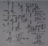
It's alive... IT'S ALIVE like Ace Ventura says!!!
About 15 minutes ago I tested my Crescendo one channel and it works....
Dio Holy Diver comes out of my test speaker....
Anyway... I still have some questions.
I think if I change those R17 & R20 to 330ohm, that will correct that BIAS problem? Correct me if I'm wrong?
I have made some measurings:
R17: 1,236V (too high)
R20: 1,238V (too high)
R8: 2,06V
R9: 2,26V
R13: 2,066V
R14: 2,26V
( in leachamp page http://users.ece.gatech.edu/~mleach/lowtim/part2.html shows that all transistors in differential stage is not necessary to be matched, so I think this is not a problem)
R8-R9: 195mV
R13-R14: 190mV
(but is this problem because voltage between those points are too high in comparison with Elektor measurements? I quess it's not a problem.)
R25: 1,3V
R27: 1,293V
G T12 - G T13: 4,26V
Elektor measurements below:
R3: 0 V;
R17,R20: 1,05 V;
R8,R9,R13,R14: 1,9 V;
between R8 - R9 (R13 - R14):< 100 mV;
R25,R27: 1V17;
Gate T12 - Gate T13: 4 V;
R34,R35 : 50 mV
Happy weekend!


About 15 minutes ago I tested my Crescendo one channel and it works....
Dio Holy Diver comes out of my test speaker....
Anyway... I still have some questions.
I think if I change those R17 & R20 to 330ohm, that will correct that BIAS problem?
Correct me if I'm wrong? I have made some measurings:
R17: 1,236V (too high)
R20: 1,238V (too high)
R8: 2,06V
R9: 2,26V
R13: 2,066V
R14: 2,26V
( in leachamp page http://users.ece.gatech.edu/~mleach/lowtim/part2.html shows that all transistors in differential stage is not necessary to be matched, so I think this is not a problem)
R8-R9: 195mV
R13-R14: 190mV
(but is this problem because voltage between those points are too high in comparison with Elektor measurements? I quess it's not a problem.)
R25: 1,3V
R27: 1,293V
G T12 - G T13: 4,26V
Elektor measurements below:
R3: 0 V;
R17,R20: 1,05 V;
R8,R9,R13,R14: 1,9 V;
between R8 - R9 (R13 - R14):< 100 mV;
R25,R27: 1V17;
Gate T12 - Gate T13: 4 V;
R34,R35 : 50 mV
Happy weekend!
Eccu said:It's alive... IT'S ALIVE like Ace Ventura says!!!
About 15 minutes ago I tested my Crescendo one channel and it works....
Dio Holy Diver comes out of my test speaker....
Congratulations!
How does it sound?
Anyway... I still have some questions.
I think if I change those R17 & R20 to 330ohm, that will correct that BIAS problem?
Given your measurements the current with 270Ohm is about 4.6mA, changing it to 330 would give appr. 3.8mA. Sounds fine to me!
I have made some measurings:
R17: 1,236V (too high)
R20: 1,238V (too high)
Which is caused by the green LEDs, changing it to 330Ohm as you suggested will produce the right current, so don't worry about it.
Difference between the R8/R9 (and R13/R14) is caused by the second stage. Nothing to worry about.
R8: 2,06V
R9: 2,26V
R13: 2,066V
R14: 2,26V
Current here (T7..T10) is about 40mA then.
R25: 1,3V
R27: 1,293V
G T12 - G T13: 4,26V
Only slightly higher then suggested by Elektor (35mA). But again: changing R17/R20 should bring this down a little.
You too!
Happy weekend!
You just built yourself a working amplifier, congrats!, you deserve a
(or two, or ...)Remco
Q1 You have normal values but since you have the "B" type of the BC550 you will get slightly more start up tranisents. This is caused by unbalance in each half between the positive and negative sections and of the input transistors pairs. I have used BC847SB/BC857BS in my monster headphone amp and I have got around 1 mV input offset and 0.25 µA total base current. The PNP/NPN pairs I have used are rather equal.
You easily test the offsets. Short C2 the you will get the voltage offset. Short C3 (disconnect the DC-servo) then you can measure the voltage across R2-R3. This will give you the input bias current. This current creates the startup transient before the DC-servo has started to work. The only way to improve the startup is to increase the time constants of R19/C7 and R16/C6. The amp itself will start slower than the DC-servo. The other solution is to use more matched input transistors and they MUST be monolithic.
Q2 "C" has higher gain, both DC and AC but BC550C/BC560C is out of production but you can choose BCx46C, BCx47C, BCx56C, BCx57C but beware of different manufactures have different data. ON Semi seems to be best. Beware of the voltage across the transistors! T7, T9 has very little, any transistor will do but the other ones, T1-T4 has 40-47 V. T5, T6 15-20 V
C type is easier to work with because the base current are smaller but B will also work but it's possible that you must "tweak" some passive components values.
Q3, Red colour has slightly lower forward voltage but if you choose green or yellow you could be forced to increase R19/R20 some but the current aren't criticical but they should be around the calculated value most so the voltages(power) across the transistors don't get too low och too high. The feedback will take care of small differencies.
Q4 No! OP77 is better in almost every respect but for this application it is of no (or minor) importance. The OP07 has power consumption which is a little bit more but the power supply can deliver the current.
If you are unsure about the currents, just measure up the whole amp when it is warmed up then I or someone else can comment the results.
It seems though that you have succeeded quite well. This is a straight forward design with no odd circuits and has been proven to be working good.
Eccu said:I changed those R17/R20 to 330ohm but voltage between testpoints tp1 and tp3 woltage was still too high at start up. 0,8VDC when trimpot was set to fully left.
Should I try change those to 460ohm like Rambi adviced?
You have only two options:
1 Make the amp start slower than the DC-servo. Increase C6, C7
2 Use relay at the output with delayed switch on.
(3 Use precision monolithic JEFT pair as input transistors, smaller bias currents)
- Status
- This old topic is closed. If you want to reopen this topic, contact a moderator using the "Report Post" button.
- Home
- Amplifiers
- Solid State
- Problems with Crescendo ME - Need help!