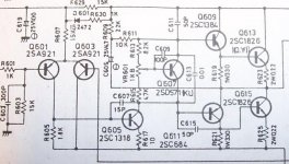
The service manual has the letters"O.Y" beside these output transistor names(Q613 is the suspect).Other transistors in the rest of the amp have letters beside them too such as"C","KL" and"RS".
What do these numbers mean?Could they refer to a certain gain group?
What do these numbers mean?Could they refer to a certain gain group?
Attachments
Left ch sounded very distorted.I put sine test tone in and positive half cycle clipped,negative half too "pointy".
Got service manual,checked bias voltage.Right ok,left no bias voltage at all( is measured across Q613 emitter resistor R623,should be 4.4mV,with no signal input)
Everything else around circuit looks OK and because fault happens only when hot or even "normally" warm I took some freezer spray and took potshots at varoius parts in the circuit to no effect untill I cooled Q613 and bias comes back immediatly and distortion goes away.
Therefore I am sort of guessing that this transistor is dodgy.
Does this make sense to you guys?
Hi,
That's fairly conclusive I guess. However are you sure your not cooling anything else. With it faulty measure the base emmiter volt drops on the driver and output. That can be revealing if one is going O/C. Don't measure from ground, measure across the junctions -- anything over 0.7 to 0.8v and it's duff.
That's fairly conclusive I guess. However are you sure your not cooling anything else. With it faulty measure the base emmiter volt drops on the driver and output. That can be revealing if one is going O/C. Don't measure from ground, measure across the junctions -- anything over 0.7 to 0.8v and it's duff.
If there is no large capacitor in series with the output to the speaker then it's DC coupled. If it uses a "split" supply ie it has a positive AND a negative rail then AGAIN it's DC coupled.
You may well be right with the output transistor theory, it's just nice to prove it")
When it does go faulty check no DC voltage appears on the output to the speaker as that can be damaging.
When it's faulty measure as I suggested, the base/emmiter volt drops on all but Q601 and Q603 in your picture. They should all be in the region of 0.7volts. Any that are significantly over and the junction is open circuit.
You can always swap the suspect one with the other channel to prove it.
Compare the voltages on the transistors with the other good channel when it's in it's faulty state and if you find anything post the readings here.
Will look in again tomorrow -- Good luck.
Edit-- Actually swapping transistors may not be a good idea -- the act of removing them can often temporarily cause them to "heal up"
You may well be right with the output transistor theory, it's just nice to prove it
When it does go faulty check no DC voltage appears on the output to the speaker as that can be damaging.
When it's faulty measure as I suggested, the base/emmiter volt drops on all but Q601 and Q603 in your picture. They should all be in the region of 0.7volts. Any that are significantly over and the junction is open circuit.
You can always swap the suspect one with the other channel to prove it.
Compare the voltages on the transistors with the other good channel when it's in it's faulty state and if you find anything post the readings here.
Will look in again tomorrow -- Good luck.
Edit-- Actually swapping transistors may not be a good idea -- the act of removing them can often temporarily cause them to "heal up"
hmm, musings/ramblings...
I may be the odd man out here, but I have never heard of a transistor that worked 'properly' when cold, but not when hot...they simply are not that type of device, once the die is cooked, it doesn't work anymore, once the bond out wires are melted it doesn't work anymore, etc...
If the transistor is overheating it can look like it's broken because it's Vbe will drop at 2mv per C, i.e. at 100C it will have a Vbe as low as 0.3-0.5v...of course the overheating may have shortened it's life to the point where replacing it is your only sensible option.
I have had transistors look like they are properly attached to the heatsink but actually not be tight because the screw was stripped, instant overheating. I've had transistors with one leg not soldered, worked properly if the board were loose, but failed as soon as the board flexed differently...
If cooling the transistor makes things work, I'd be looking for a mechanical/electrical cause, the freeze spray may make a bad solder joint close up and 'work', it may make a lousy thermal connection less apparent etc.
None of this means you should not consider changing the output transistors, but root causing the problem can help you avoid the same problem later.
HTH
Stuart
Hey Stuart,I will check that out too.
The first thing I tried to fix the disappearing bias was to resolder the whole left ch. power output circuit.This actually worked for a day or two and by that time it was back in the house and I thought I had fixed it.
When it distorted again I thought that it was because the house was warmer than the garage and so the bias needed re-adjusting.However I found no bias voltage and hence my faulty transistor theory.
Anyway,when I re-soldered I just went over the old solder with new.I will remove the old solder now and use fresh stuff.
Re: hmm, musings/ramblings...
Hello Stuart,
I can assure you they do fail intermittantly. Ask any experienced technician
I spent all my working life in electronics, in the service side of things actually, and it is a common mode of failure. It's quite common to see a transistor, for example with emmiter grounded and perhaps a 6 volt positive going drive on the base. Unsolder it test it -- not that it need's it as the above is conclusive in itself -- and it will read OK. Put it back and the thing works.
It almost certainly is due to an intermitant bond between the die and the fine wire connecting with the die but it's a very real effect nonetheless.
Five minutes work with the amp faulty measuring the voltages on the junctions should locate the fault.
Regards Karl
Hello Stuart,
Stuart Easson said:I may be the odd man out here, but I have never heard of a transistor that worked 'properly' when cold, but not when hot...they simply are not that type of device, once the die is cooked, it doesn't work anymore, once the bond out wires are melted it doesn't work anymore, etc...
Stuart
I can assure you they do fail intermittantly. Ask any experienced technician
I spent all my working life in electronics, in the service side of things actually, and it is a common mode of failure. It's quite common to see a transistor, for example with emmiter grounded and perhaps a 6 volt positive going drive on the base. Unsolder it test it -- not that it need's it as the above is conclusive in itself -- and it will read OK. Put it back and the thing works.
It almost certainly is due to an intermitant bond between the die and the fine wire connecting with the die but it's a very real effect nonetheless.
Five minutes work with the amp faulty measuring the voltages on the junctions should locate the fault.
Regards Karl
Stuart Easson wrote
I have seen one like that. This was after years of use of the stereo.
Hit the transistor on the table and occasionally it showed incorrect dide tests.
I have even seen a diode that cold tests ok everytime but does not work in the circuit.
Gajanan Phadte
I may be the odd man out here, but I have never heard of a transistor that worked 'properly' when cold, but not when hot...
I have seen one like that. This was after years of use of the stereo.
Hit the transistor on the table and occasionally it showed incorrect dide tests.
I have even seen a diode that cold tests ok everytime but does not work in the circuit.
Gajanan Phadte
gmphadte said:Stuart Easson wrote
I have seen one like that. This was after years of use of the stereo.
Hit the transistor on the table and occasionally it showed incorrect dide tests.
I have even seen a diode that cold tests ok everytime but does not work in the circuit.
Gajanan Phadte
Such transistors are a good candiate for the widlarizing process me thinks

I once worked as a repair tech in satellite reciever factory and we came across many odd types of component failures.We did not"Widlarize" them,instead we "punished" the naughty parts that sometimes gave us headaches for hours trying to find them.
Dropping them in a solder pot or wave solder machine was my personal favorite.
Dropping them in a solder pot or wave solder machine was my personal favorite.
No.
I removed the old solder and re-soldered the whole left power stage.No change.
When OK, b-e voltage is 0.6v on all TR's(I did not check the input or feedback TR)
When faulty b-e voltage on Q613(the suspect) is about 3.5vdc and strangely the b-e volts on the driver TR(Q611) for the OTHER output TR(Q615) goes up to about 2.4vdc.Cooling this driver has no effect.
Still,only cooling Q613 with freezer spray cures fault.I have ordered some new 2SC1826's but I don't know what gain group they are.
If they are a different gain will this drastically effect my amp or will bias voltage adjustment be different value or what?
mooly hit the nail, a busted lead out wire moving as it heats up. quite common in everything from transistors to diesel glow plugs !
I would think Q615 gets 'reversed' biased (did you note to polarity when you measured ?) as a result of the failure of Q613. 2.5 volts shouldn't make it avalanche so its it may be OK
I would think Q615 gets 'reversed' biased (did you note to polarity when you measured ?) as a result of the failure of Q613. 2.5 volts shouldn't make it avalanche
so its it may be OK- Status
- This old topic is closed. If you want to reopen this topic, contact a moderator using the "Report Post" button.
- Home
- Amplifiers
- Solid State
- One faulty output TR,change all 4?