Looking for an intermittent phono socket connection on my Cyrus 2, I removed the PCB, cleaned it up, and put it back. I didn't tighten up the heatsink power transistor mounting "bars" as I thought to check for specific torque settings first.
Needless to say, I then did a very dumb thing - forgot, and put it back together. After around 30 minutes use, it stopped.
Checked the PSX, and both 4A quickblow fuses had gone. Replaced those, and they just went again. So something is now shorting out the power rails.
I am guessing the the power transistor pairs (PT77s) are probably what's gone. My questions are really around where I should begin. Should I
- Just replace the PT77s with equivalents (richie00boy recommends MFE340/MJE350 on another thread here)
or
- desolder the PT77s, power up the rest of the amp. Will it be stable (i.e. not for music purposes, but just to make some simple tests e.g. fuses no longer blow)?
or
- desolder the PT77s, test them on my multimeter Hfe tester, but not power up the amp until I have installed replacements?
All contrib's welcome, particularly from you guys who really know the insides of the Cyrus.
It's a rev07 by the way. Can post pics if it will help.
Steve
The MJE340/350 are for the drivers not the output devices.
I can say now that you will have blown the output devices by doing what you did.
You will need to replace the drivers as well as the output devices as usually the output transistors blowing will take them out or at least damage them.
I can say now that you will have blown the output devices by doing what you did.
You will need to replace the drivers as well as the output devices as usually the output transistors blowing will take them out or at least damage them.
Thanks for your reply, I will do as you suggest.
For the output devices I think you mentioned in the other post that the Cyrus recommended replacement is BUV48A, and an alternative is TIP35C.
Looking at the datasheets on the Farnell website:
BUV48A
http://uk.farnell.com/9936122/semiconductors-discretes/product.us0?sku=stmicroelectronics-tip35c
TIP35C
http://uk.farnell.com/9936122/semiconductors-discretes/product.us0?sku=stmicroelectronics-tip35c
BUV48A is rated for higher Vce0 (higher than needed), and DC current gain of around 25-40 (temperature related). As it's a switching part, it is fast (but specified in terms of switching time, not Ft).
TIP35C is a general purpose device. Vce0 looks to be adequate (100v) for the +/-40V rails but without too much to spare. Looks to have higher current rating, Ft=3MHz.
Not that much to choose on price, given the £20 minimum order value. The TIP35Cs are £1.21 each, BUV48A's are £2.63 each.
Apart from price, are there any sonic differences?
(Just going to look for the driver devices now).
Just been to look at my amp. Driver devices appear to be MJE243 / MJE253.
Comparing specs for the suggested replacement MJE340/MJE350, seems like the existing parts are slightly more robust in some respects - Ic max = 4A, rather than 500mA for the replacements.
Farnell seem to carry all of the above, so I wonder if it's best to go for MJE243/253 as per originals.
MJE243:
http://uk.farnell.com/jsp/search/br...nsearch_001&Ntt=mje243&Ntx=&_requestid=132845
MJE253:
http://uk.farnell.com/jsp/search/br...nsearch_001&Ntt=mje253&Ntx=&_requestid=132605
I've not heard of ON Semiconductor, are they OK?
BTW I am just using Farnell as a reference point here, because (a) they sell to individuals and (b) the parts seem to be precisely identified and described, with manufacturer's own data sheets. I'm sure there are other good suppliers as well.
Just before you go crazy and paranoid, things like this can be repaired systematicaly.... look up transistor diode test in google... once you understand it, remove and test transistors one by one, solder good ones back in board and mark them as you progress... blown ones need replaceing.
")
Sorry I gave the wrong link to the BUV48A, it should be
http://uk.farnell.com/jsp/search/br...nsearch_001&Ntt=buv48a&Ntx=&_requestid=133516
http://uk.farnell.com/jsp/search/br...nsearch_001&Ntt=buv48a&Ntx=&_requestid=133516
Have ordered the parts.
Will it be necessary to check or trim the quiescent current in the output stage, after replacing the devices? I'm an analogue novice, but I guess that R81, 130R plays some trimming role.
Presumably also worth checking output for DC offset?
I found some tips by Destroyer_x in the forum, regarding his testing of his own designs - to temporarily replace PSU rail fuses with 10R power resistors using croc clips. Then flick the power on, make a quick check, then flick it off again - avoiding meltdown of parts in case of secondary faults etc. Is this a good idea?
Also purchased some 50W 8R2 resistors, which I can put on a spare heatsink. Once it's running OK with a clean signal coming out, I thought to try it into these, before connecting real speakers. Is that also a good idea?
Any other tips?
Update:
Parts arrived, fitted and powered on - so far so good.
On 1 channel, both output devices, and 1 driver, were definitely dead (short circuit C-E, once tested when out of circuit).
I replaced all output device pairs, and the driver pair on the dead side. I left the drivers on the OK side, as I don't think they should have been harmed by the runaway incident on the other channel. They would have just seen a sudden loss of power. Do you agree?
With inputs shorted, and safety PSU resistors fitted in series with the fuses, I watched the bias current (indirectly, by watching the voltage across R107 / R108). Slowly creeps up to around 10mV each half, after about 30 minutes starting from cold.
R107 = R108 = 0.22R. So my bias current is, I think, around 45mA after half an hour.
At this stage, DC offset on the speaker output terminal is around 5mV on each channel. Do you think that's OK?
I made up some 50 watt, 8 ohm dummy loads, connected them, and I get a nice clean signal out. (Input signal is coming from a home made CD test disc with 1kHz sine, square and triangle waves).
Max output seems to be around +/-30V pk-pk. No smoke! Dummy loads get nice and warm, amp heatsink also warms up 'normally'.
Just looking at the zero crossing point on a scope, with a triangle waveform input, seems perfectly straight without any obvious crossover distortions. (Although is this probably too coarse a test to tell?)
if anyone has access to the service manual for a Cyrus 2, it would be great to learn if there are any specific setup procedures I should follow.
Also from those of you with more amp experience (I think that's just about everyone in this forum!) whether the above values / experiences seem normal.
Thanks v. much, sorry for the long post. If it is of general interest I could post some pictures etc. and my test disc as an ISO file somehow. (I made it using Goldwave - very easy to do).
That all sounds fine. If the other channel did not blow the outputs then I think you are OK not replacing the drivers. But yes you definitely needed to replace the outputs as they would probably let go in the not too distant future if you hadn't.
The service manual is available from Cyrus and costs £17 a couple of years ago when I got mine. It doesn't tell you a great deal to be honest though, if fact I'd say it's fairly poor. Just a quick overview of the revision differences and some schematics.
I can't remember what the bias should be and my manual is at my other house. Are you getting about the same bias on each channel? If it looks OK on the scope and sounds OK then I'd tend to leave it. Certainly 45mA seems generally acceptable.
The DC offset sounds good at 5mV.
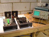
About to connect the amp back to speakers and try it out. Here are some pics showing the job underway, which I thought might be of some use/interest to someone following along later.
Firstly, the amp + PSX with lids off, after repair. Home made dummy loads in the background. These are 8R2 metal cased power resistors, rated at 50W, mounted on to some old spare quite large heatsinks.
I used thermal paste (left over from a PC processor installation) to get a good coupling of the dummy loads to the heatsink.
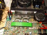
On the Cyrus, I did not replace the heat-conductive insulation between the new output devices. However i did verify - before powering up - that I had no conduction between any of the BU48A device metal tabs and the case.
I borrowed the scope from a friend! Very nice it is too.
The input signal is coming from a portable CD player, not shown.
Firstly, the amp + PSX with lids off, after repair. Home made dummy loads in the background. These are 8R2 metal cased power resistors, rated at 50W, mounted on to some old spare quite large heatsinks.
I used thermal paste (left over from a PC processor installation) to get a good coupling of the dummy loads to the heatsink.
On the Cyrus, I did not replace the heat-conductive insulation between the new output devices. However i did verify - before powering up - that I had no conduction between any of the BU48A device metal tabs and the case.
I borrowed the scope from a friend! Very nice it is too.
The input signal is coming from a portable CD player, not shown.
Attachments
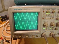
Low-level signal handling (200mV per division). The scope display automatically corrects for the 10x probes.
Looks nice and linear to me ...
Not shown here, but with volume control at max and a loud (50% digital range) input signal, the amp just starts to clip, at around +/-30v pk to pk.
Looks nice and linear to me ...
Not shown here, but with volume control at max and a loud (50% digital range) input signal, the amp just starts to clip, at around +/-30v pk to pk.
Attachments
Hi, yes the insulation is still there. Maybe I wasn't very clear in my first description.
What I meant was - it's still the original insulation. I have not renewed/replaced it with new insulation.
I read in another post that someone recommended replacing it with mica washers + paste. I haven't done that. As long as it stays electrically insulating, and thermally conducting (and not the other way around) then I am happy!
- Status
- This old topic is closed. If you want to reopen this topic, contact a moderator using the "Report Post" button.
- Home
- Amplifiers
- Solid State
- Oh dear, I killed my Cyrus 2. Where to start faultfinding?