hi,
i saw this circuit for 25w class a. but problem is VR1 have to set for class-A 1.5amp quiescent current. if the current is low it will switch to class AB. i want to make it only for class-A. how can do this? how to i check my quiescent current is 1.5a? i only have multimeter.
http://sound.westhost.com/project3b.htm
i posted the circuit design.
thanks
Attachments
Good choice, space2000
As usual, no problems to find the transistors, when go for Rod Elliott Projects.
BC546 and MJL4381A and MJL4302A should be easy.
And if you do not find those MJL you may use several other similar:
2SC1381 and 2SA1302
even popular
2SC5200 and 2SA1943 would work well, I think
1.5 Ampere is not a bad choice for 2x25 Volt Class A into 8 Ohm
As this output is push-pull, the max theoretical output is 3.0 Ampere (2x1.5)
25 Volt/ 8 Ohm ~ 3 Ampere
I = U / R
Ampere = Volt / Ohm
When you have 0.5 Volt across R13
or
1.0 Volt across R13+R14 .. then is 1.5 A idle Class A current
The heatsink must take 50 Volt x 1.5 Ampere = 75 Watt
A good heatsink size would be something like 1-2 kilo in weight .. or more.
Lineup new website = CLICK
lineup said:the max theoretical output is 3.0 Ampere (2x1.5)
You meant to say : the maximum output current for CLASS A operation is 3A.
25W continuous in 8 Ohm is 50W peak, which corresponds to an output current of 2.5A=> requires a quiescent current level of 1.25A.
1.5A quiescent is 3A peak Class A output current for a push pull output stage=> in a 4 Ohm load the output stage then operates in Class A to an output level of 3x3x4=36W before it crosses over to Class AB.
Where Mr Elliot gets the 9W/4 figure from is beyond my grasp of reality.
Full Class A operation in a 4 Ohm load requires a quiescent current level of 2.5A.
=>50W continuous output in 4 Ohm is 20V theoretical peak output voltage, 20/4=5.
For 25V rails, a quiescent current level of 2.5A corresponds to an output stage dissipation of 125 Watts.
The regular plastic 2-device output stage of the P3A will be unable to handle 125W of heat.
The only option for that would be to use Sanken MT200 devices, my ExtremeA power amps dissipate a total of 520W with 8 devices.
But that also requires Extreme fan operated heatsinks to keep the die temperature of the output devices at a safe level.
With "normal" heatsinks, you'd have to double the number of output devices of the P3A to 4 per channel and use 0.25C/W heatsinks.
Rod Elliott is measuring across both resistors.
Quoted from ESP
"When you are satisfied that all is well, set the bias current. Connect a multimeter between the collectors of Q7 and Q8 - you are measuring the voltage drop across the two 0.33 ohm resistors. The correct quiescent current is 1.5A, but I strongly suggest that you use a lower current to start with! The voltage you measure across the resistors should be set to 500mV ±5mV"
jacco vermeulen said:500mV across two 0.33 Ohm resistors is 0.75A.
Yes, but those giong to tell Rod?
He state's he measures between the collectors.....
hi,
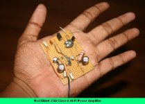
i was curious about the sound quality. its impressed me very much...wow...wow. i just made a dummy model and checked the sound quality. ofcourse it is not final. just made a vb circuit. so cute and small....ha....ha......its really works no hum and distortion at all...like a little baby in hand.
here is the pic.
Attachments
Hi,
the amplifier section of this will cost just a few pounds.
The heatsink and PSU will each cost far more.
1.5A bias current is just about right for a push pull ClassA amplifier driving an 8ohm load. It should give around 25 to 30W into 8r0 and stay in ClassA.
If you demand more current (>3Apk) it automatically moves into ClassAB on the high current transients, if the PSU is properly scaled to deliver such transient currents.
I would suggest 300VA and >=+-30mF/channel for 8ohm speakers.
1pair of outputs dissipating ~75 to 80W will run very hot,
fitting a temperature cut-off switch may be a good idea. Latching rather than reset on cooling.
As for circuit mods, I would prefer to see emitter resistors added to Q1, Q2 & Q4. Add a trimmer to either R6 or R7 to ensure the LTP is actually balanced. I would change C1 to 3u3F or 4uF and C3 to 150uF.
Q.) is 2.8mA through the drivers sufficient? 10mA or maybe even as high as 30mA seems more suitable.
you have been told how to measure the bias in other threads.Originally posted by space2000
how can i check bias current with multimeter?
Hi
To measure the bias current you need to measure the voltage drop across r13 or r14 and apply the formulea V = IR. Other threads do give details of this. If you go this route do start with VR1 at a high value and slowly reduce the value of VR1 to increase the bias current slowly.
However when doing that do not forget to check the temperature of the heatsinks around where the output transistors are attached. Whatever the bias current is you do not want the heatsink temperature to rise above the point where you can not keep your hand on the heatsink for at least 10 seconds. The heatsink may take an hour or so to reach final temperature.
You will find a good article on "Passdiy" about this. The other articles there are also worth reading.
I hope you enjoy the amplifier; the circuit looks ok.
Don
space2000 said:hi,
its impressed me very much...wow...wow. i
Very interesting. Especially that you say this after building the Aleph monster.
Btw, your enthusiam for trying out new things is very refreshing and impressive.
analog_sa said:your enthusiam for trying out new things is very refreshing and impressive.
Dildo
space2000 said:hi,
i was curious about the sound quality. its impressed me very much...wow...wow. i just made a dummy model and checked the sound quality.
here is the pic.
Hi Space,
Congrats once again! Your excitement is pulling me
") , it seems you are getting more and more satisfied with your amps discovery. How do you compare now the sound quality/accuracy of your previously constructed class-A aleph and this simple one?
, it seems you are getting more and more satisfied with your amps discovery. How do you compare now the sound quality/accuracy of your previously constructed class-A aleph and this simple one?B.regards,
mannycc
Hi mannycc,
I made just for curious as it is nice cute very easy to build. Ha….ha…..Hot….really hot. It is working fine but haven’t yet final for sound quality to compare with aleph-3 as its require to adjust fine bias and some fine tuning. I just got my oscilloscope so will take time to have full version of sound test. Anyway I found this two amp sound are different then each other but aleph-3 sound is much sweeter then this amp. Anyway, this is not right to tell about sound quality until I set the bias properly.
I made just for curious as it is nice cute very easy to build. Ha….ha…..Hot….really hot. It is working fine but haven’t yet final for sound quality to compare with aleph-3 as its require to adjust fine bias and some fine tuning. I just got my oscilloscope so will take time to have full version of sound test. Anyway I found this two amp sound are different then each other but aleph-3 sound is much sweeter then this amp. Anyway, this is not right to tell about sound quality until I set the bias properly.
That's great man, wow! can't believe you also get your own oscilloscope Sorry i'm in no position to say something about the oscilloscope since i got a hand of it 2 or 3 times only in my life, good thing lot's of help you can get from the thread from the people with tremendous knowledge and experience with same interest!
The reason i asked you about the class A amps is because i also get alot of positive infos regarding its sound quality compared with other classes, now i try to follow some thread about class D amps (out of curiousity) because of its promising sound quality with the new semicons design, but anyway class A appears to be the best when it comes to sound faithful reproduction, just not to mention the heat it can generate
I used to be so interested with the tone equalizations and collect diff circuit diagrams (passive, active, transistors, chips...) analize a little bit but not design, but now i realized that its not good to alter the sound from original, now it feels like face with too much make up..ha ha ha! not natural.
Regards,
mannycc
Sorry i'm in no position to say something about the oscilloscope since i got a hand of it 2 or 3 times only in my life, good thing lot's of help you can get from the thread from the people with tremendous knowledge and experience with same interest!The reason i asked you about the class A amps is because i also get alot of positive infos regarding its sound quality compared with other classes, now i try to follow some thread about class D amps (out of curiousity) because of its promising sound quality with the new semicons design, but anyway class A appears to be the best when it comes to sound faithful reproduction, just not to mention the heat it can generate
I used to be so interested with the tone equalizations and collect diff circuit diagrams (passive, active, transistors, chips...) analize a little bit but not design, but now i realized that its not good to alter the sound from original, now it feels like face with too much make up..ha ha ha! not natural.
Regards,
mannycc
mannycc said:The reason i asked you about the class A amps
is because i also get alot of positive infos
regarding its sound quality compared with other classes,
now i try to follow some thread about class D amps
because of its promising sound quality with the new semicons design,
but anyway class A appears to be the best
when it comes to sound faithful reproduction,
------------------
Regards, mannycc
Hello mannycc.
Do not think we met. But space2000 I have discussed with.
Besides, he is such a lovely man. He really likes doing diyaudio
-----------------------
Do not be hanged up on any 'Class' sounds this or that.
Or is better than other 'Class'.
Because this is not so.
Also notice that I put 'Class' within quotes.
Because there is no such thing, as one 100% Class B, D, C, H or A.
And if there is one true Class A or one True Class AB or true Class D
each amplifier will have different test data parameters.
Not two Class A are the same
.. not even 2 from same identical schematic, with same trasistors and everything.
Because there is NOT 2 transistors, for example, that are identical.
Even in your stereo.
Your left amplfier is not making same output, as your right amplifier.
Close maybe, but not 100 % .. more like 97.3 % I would say :d
Not two Class A amplifiers are same design.
Nelson Pass Class A is one thing.
Lineup Audio LAB Class A amplifiers is another thing.
It is not the class that makes good/bad.
It is the good/bad design idea + building of the amplifier
that makes any amplifier good/bad.
Hi Lineup,
No, we never have exchanges before. Thanks for your interesting ideas and know-how. I have no doubt Space is a good natured and fun loving gentleman!
These past days, i'm reading alot of new informations about different kinds and class of amps, theories and principles how to make a perfect amp although theres no such thing, but perhaps the complicated and hard to understand technologies are going to that direction in the far future, of course i cannot equate perfect amp from perfect sounding amp because its two different thing - just like cause and effect or supply and demand, two dfferent thing but one will not exist without the other.
Many amp buiders (and buyers) came to the point of real satisfaction with the sound quality their amps produced and that's the most important, the satisfaction although temporary. In reality, sooner or later they will realize that there's one amp in their neighbors house that is better sounding and will say wow!after that he will feel unsatisfied and will do more searching and the process goes on and on.. maybe that's one reason most audio lovers have more than one amp in their possession..
Fully understand your points, another thought i consider though is... for properly designed, constructed, and biased amps it will appears one class has more sonic advantage/diasadvantage over the other using same speaker, also if we can make or design (not me) an amp of same stages but with less part that can amplify the original input signals with less distortion over the load then why not?, just as Space is discovering (will discover?). But it appears never to be the case in reality as you can see with high end expensive amps and that brings my curiosity with the potential of class D amps, but every coin has 2 sides..
Regards,
mannycc
- Status
- This old topic is closed. If you want to reopen this topic, contact a moderator using the "Report Post" button.
- Home
- Amplifiers
- Solid State
- making 25w constant class A amp