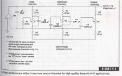
Hello all. I have a home built preamp that I'd like to add a 3 band eq to. I have been looking at an eq schematic presented in G. Randy Slone's "The Audiophile's Project Sourcebook". Attached is a scan of his schematic (please don't kill me for copyright infringement).
I'd like to use this design, because it seems simple and Slone says it works well. I intend to include a bypass also, of course. However, this is the first time I've wanted to build something without a pre-fab PCB. Having trouble with P2P wiring a short while ago, I think home-fab PCB shouldn't be too hard for this project and might be interesting.
I thought It would be easy until I figured out that Slone's schematic is for ONE channel of audio. I want TWO! I've tried using Eagle PCB Layout Editor to get a board schematic started, but am slightly confused as to how to proceed.
Could someone offer me a hand in this? I will include my *.sch file from Eagle.
I am open to changing the EQ circuit if necessary. I guess the two parts I really could use some help on are:
- finishing the schematic
- tips on using Eagle software (I'm finding it hard to get into!)
Thanks!
Attachments
SCH file
Here's my *.sch file if someone wants to check it out ...")
It's not complete; I stopped when I couldn't figure out how to copy one channel completely and then attach necessary points to the stereo pots.
** obviously this is not a txt file, but I couldn't upload here unless I added a dummy extension to the file **
Here's my *.sch file if someone wants to check it out ...
It's not complete; I stopped when I couldn't figure out how to copy one channel completely and then attach necessary points to the stereo pots.
** obviously this is not a txt file, but I couldn't upload here unless I added a dummy extension to the file **
Nordic said:To copy and paste a group, first select the group then use the icon that looks like a scissor.... I know this normally represents cut.. but trust me, in eagle, it copies.. then use the paste icon...
Hey thanks! That worked great. This program isn't very intuitive... Your suggestion has helped me along greatly.
My new question is how do i know what the pinouts of a stereo pot are?
hi meaghers,
I can't open your schematic for some reason, so I'm guessing you have used a variable resistor which has only 3 connect points.
You need to use a dual pot component. If you pick the right component, it will place the first variable resistor then the next. It will be named something like P1A and P1B. On the schematic it will appear as two components, but on the PCB it will only be one.
regards
- Status
- This old topic is closed. If you want to reopen this topic, contact a moderator using the "Report Post" button.