Hello guys!
I´m new to this forum, but really glad I found it!
I have been thinking of designing an amp including Mr Cordells error correction output stage, and a symmetric twin differential input/driver. My question is, would the Toshiba 2SJ201/2SK1530 be suitable for the Hawkfords error correction approach? And alsp important, are they lateral? I would like to benefit from the self protecting characteristics at high currents. It would be wonderful not having to use non transparent protection circuitry. I know they have slightly positive temperature coefficient, but that´s no problem. I plan to use only the standard zener across gate/source as protection, and maybe a pair of schottky diodes at the output.
")
I´m new to this forum, but really glad I found it!
I have been thinking of designing an amp including Mr Cordells error correction output stage, and a symmetric twin differential input/driver. My question is, would the Toshiba 2SJ201/2SK1530 be suitable for the Hawkfords error correction approach? And alsp important, are they lateral? I would like to benefit from the self protecting characteristics at high currents. It would be wonderful not having to use non transparent protection circuitry. I know they have slightly positive temperature coefficient, but that´s no problem. I plan to use only the standard zener across gate/source as protection, and maybe a pair of schottky diodes at the output.
About Lateral or Vertical for 2SK1530 / 2SJ201
we have discussed this a number of time = search forum
http://www.diyaudio.com/forums/search.php
>>> 2SK1530 lateral
In my opinion they are more lateral if we look at main characteristics.
Anyway, they are very good powerful mosfet.
Quite easy to drive (not too much current needed).
About temp coefficient.
I would use some vbe compensation voltage (not pure resistive output bias control).
About Hawkford / Cordell Error correction approach with these
it is better Robert Cordell will answer you on this
Besides I do not use such fancy corrections .. only normal feedback correction.
lineup said:About Hawkford / Cordell Error correction approach with these
it is better Robert Cordell will answer you on this
Besides I do not use such fancy corrections .. only normal feedback correction.
Don't be misled, "Hawksford EC" is normal feedback. Cordell's circuit is just a bizarre way of implementing NFB.
The difficulty you will have, Rikard, is with the low Vgs thresholds of those FETS, 0.8V to 2.8V. The Cordell circuit requires 2V or more. So to Use those FETs you would have to have to pick two with above average Vgs th, and preferably very close to one another. If that is not practical, you should use a simpler implementation of local NFB.
Ok, so the lower drive voltage will make the HEC ineffective? If so, a simple resistor voltage divider to the gates would make the drive voltage seen by the HEC circuit just as it was originally designed.
Well, I´m gonna have a try at least.
PS. I agree that Cordells circuit is a kind of local NFB. But nonetheless it seems very effective. I was also thinking of developing something that never lets the current drawn by the FETs down to zero. Technically this would still be class A operation, but not that ineffective. maybe somebody has already done this? (Not simply raising the idle that is)
Leach and a few others claim that preventing the inoperative device in the Push-Pull Topology from actually turning off is ClassA. They are wrong.Rikard Nilsson said:I was also thinking of developing something that never lets the current drawn by the FETs down to zero. Technically this would still be class A operation, but not that ineffective. maybe somebody has already done this?
Both devices must be actively controlling the output to be classed as being in ClassA.
But if the "inoperative" device is not completely turned off it will still control the output to some degree, right?
As far as I know, if we never completely turn of any of the output FETs, it is technically known as class A operation. Still, I consider this "politics", the important thing is to get rid of any crossover distorsion.
As far as I know, if we never completely turn of any of the output FETs, it is technically known as class A operation. Still, I consider this "politics", the important thing is to get rid of any crossover distorsion.
If I can use Class A, for the power I need to my speakers
than I use Class A push-pull.
If I have good sensitivity speakers ( 90-96 dB SPL )
and normal sized home living room for listening,
I have no problems using my Class A amplifier output stages
No lack of power, whatever, for Hi-Fi audio performance
If Class A is impractical = too much idle power (say for me is >=60 Watt Idle per channel)
than I go for 'normal Class AB'
... as you say, to remove as much crossover effects as possible
no,Rikard Nilsson said:But if the "inoperative" device is not completely turned off it will still control the output to some degree, right?
As far as I know, if we never completely turn of any of the output FETs, it is technically known as class A operation. Still, I consider this "politics", the important thing is to get rid of any crossover distorsion.
if the nearly turned off, but not quite, device is simply passing constant current then it is not controlling the output current/voltage. The push pull is operating as Push or Pull depending on which device is idling.
That is no better than ClassAB and may be worse if the bias has been set to other than optimum ClassAB (Vre between 15mVre and 25mVre).
Rikard Nilsson said:Ok, so the lower drive voltage will make the HEC ineffective? If so, a simple resistor voltage divider to the gates would make the drive voltage seen by the HEC circuit just as it was originally designed.
Yes, you can address the gate voltage by reducing the transconductance by a factor of 2 or 3.
traderbam said:
Don't be misled, "Hawksford EC" is normal feedback. Cordell's circuit is just a bizarre way of implementing NFB.
The difficulty you will have, Rikard, is with the low Vgs thresholds of those FETS, 0.8V to 2.8V. The Cordell circuit requires 2V or more.
Rikard Nilsson said:Ok, so the lower drive voltage will make the HEC ineffective? If so, a simple resistor voltage divider to the gates would make the drive voltage seen by the HEC circuit just as it was originally designed.
PS. I agree that Cordells circuit is a kind of local NFB. But nonetheless it seems very effective.
Dear Rikard,
Over the past days, I did some PSPICE simulation work according EC, the influence on THD and performance, in comparison to "normal" emitter/source follower or complementary feedback stages.
Well, Cordell's circuit IS a kind of feedback, but not NFB. Usually, you use a high-gain stage, and amplification is reduced by using negative feedback.
Error Correction means, your amplifier stage has a gain factor lower than 1, but you add the error voltage to the input of that amplifier stage. So you will get a unity gain factor.
Cordell's circuit is very effective! Jan Didden used a Current Conveyor, which means the same except of two inverted signals.
But Cordell's circuit will not work with low bias voltages, because the transistors which calculate the error signal between the output stage's input and output signal will have too low voltage.
I think, a voltage divider connected to the gates will not be very effective, because of the voltage drop during transients.
I did some considerations and changed the EC circuit, so it will work with low bias voltages. I will show you in a few hours, when I have access to my computer at home.
regards,
Guthorst
Guthorst said:Well, Cordell's circuit IS a kind of feedback, but not NFB. Usually, you use a high-gain stage, and amplification is reduced by using negative feedback.
Error Correction means, your amplifier stage has a gain factor lower than 1, but you add the error voltage to the input of that amplifier stage. So you will get a unity gain factor.
No it doesn't. Cordell's circuit effectively puts the loop gain in the FB path rather than the forward path, that's all. This is commonly called a servo circuit. It is NFB just the same. There is no more "error correction" going on than there is in ANY other NFB circuit.
By all means base the choice of Cordell's circuit upon number of transistors or other implementation attributes, but don't fool yourself into thinking it is anything other than localized NFB.
Cordell borrowed the term "error correction", which is a misnomer, from a paper by Hawksford which presents a simplistic and theoretical mathmatical model, including both negative feedback and feedforward elements.
to remove as much crossover effects as possible
Lineup, may I correct you on this one?
In ClassA crossover distortion simply does not exist at all, since no output device shuts off at any time. It is not only reduced; see D. Selfs webpage for more info.
What you refer to is ClassAB, where increasing the bias reduces crossover distortion up to a certain point - the optimum bias - and increases if one further increases the bias current.
Have fun, Hannes
PS: Cordells amp is error-dependant local NFB.
h_a said:PS: Cordells amp is error-dependant local NFB.
Only if you claim ALL NFB systems are error dependent.
The notion that the amount of feedback, ie: the feedback loop gain, varies with the error is incorrect. Do the maths, do the sims.
Wow! interesting response here! Everybody seem to have their own opinion. About the voltage divider, I came to think of putting a couple of diodes in series with the gates (before the gate resistors) as part of the divider in order to drop the voltage to the FETs, enabling the HEC circuit to operate at its intended level. Of course, parallelling the diodes with caps would get rid of any noise and most of any fluctuating voltage drop.
I´ll check it in the EW. Too bad I don´t have the mentioned FETs as models though.....
I´ll check it in the EW. Too bad I don´t have the mentioned FETs as models though.....
traderbam said:
Cordell's circuit effectively puts the loop gain in the FB path rather than the forward path, that's all. This is commonly called a servo circuit. It is NFB just the same. There is no more "error correction" going on than there is in ANY other NFB circuit.
By all means base the choice of Cordell's circuit upon number of transistors or other implementation attributes, but don't fool yourself into thinking it is anything other than localized NFB.
Dear traderbam,
that sounds interesting. Because the forward path has a less than unity gain, and the result should be unity gain, there must be something in the feedback path to increase gain. Doesn't that mean "Positive Feedback"?
In contrast, the Complementary Feedback Pair has a high open loop gain, and it uses conventional NFB. But it shows worse THD+Noise than Cordell's EC.
I think, the best way to influence THD is to improve the output stage. Because it has most contribution to non-linearity, and depends on output load, output current and non-resistive loads have to be taken into account.
But the output stage should be optimized without using too many transistors or other components, which may result in a negative impact to noise or performance.
regards,
Guthorst
I agree that it´s the output stage that introduces most of the distorsion and other problems. As Cordell writes, the output is where large currents and high voltages meet, and that´s where problems are likely to occur.
The rest of my prototype is fairly straightforward, two differential pairs and two predriver transistors. All in class A, so no problems with distorsion.
Maybe I should upload the EW file here?
The rest of my prototype is fairly straightforward, two differential pairs and two predriver transistors. All in class A, so no problems with distorsion.
Maybe I should upload the EW file here?
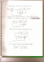
Guthorst said:Because the forward path has a less than unity gain, and the result should be unity gain, there must be something in the feedback path to increase gain.
Here's something I posted in the Cordell error correction thread a couple of years ago. Using Hawksford's simplified model, it shows where the "infinite" loop gain comes from.
Attachments
Dear Rikard,
This is a first proposal from my last design I'm working on. It's a current conveyor, like Jan Didden used. I didn't want to use integrated circuits, and only a small number of transistors. The design is not finished yet, some bias voltage components have to be replaced - I inserted DC voltage sources to simplify the design. And a frequency compensation is essential, because above 1MHz, gain increases dramatically.
Its not a complete amplifier, input differential pair and VAS stage are missing. I only want to optimize the output stage.
THD+Noise for that Error Correction and Output stage is near 0,04% at 20kHz, 25V_peak and 8 Ohm load. Components are not optimized yet. And adding the input differential pair and VAS, and applying an overall NFB will reduce THD.
I'm used to calculate THD at 20kHz, because Douglas Self showed that it is easy to design a good performance at 1kHz, but it's a higher challenge to give good performance at 20kHz.
Regards,
Guthorst
Attachments
Looks interesting!
I like symmetrical designs, something tells me non symmetricals are not as good, eventhough I have seen many very nice amps that are not symmetrical...
So, here is my prototype. I have built one but not using the error correction stage. I get ok performance from it, but would like to see this EC work.
I zipped a gif screenshot, hope it opens ok.
Attachments
- Status
- This old topic is closed. If you want to reopen this topic, contact a moderator using the "Report Post" button.
- Home
- Amplifiers
- Solid State
- Designing amp with 2SJ201/2SK1530