
Very nice amp you did")
I am working on a similar topology: current feedback jfet input and mosfet output.
I have some questions.
What is the power rating?
What class of operation?
Have you tried one unit with 5 pairs of output transitors to compare with the one you show here (3 pairs)?
Is it a "split" feedback (overall from output stage and some before the output stage, I refer to R50 and R51 purpose)?
Thanks
Hi Fab,
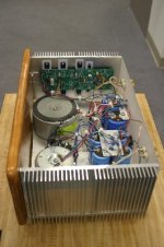
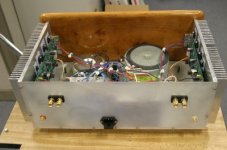
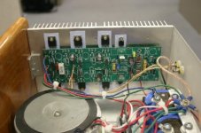
Power rating is 100w with about 56v rails.
The amp is a high bias AB design but you can run it full class A if you lower the rails.
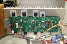
I use 5 pairs of outputs with low z loads but it runs fine with three pairs.
If you use R50 and 51 you can leave out R49 and leave the output stage outside the feedback loop. You could possibly run it with split feedback but I have not tried it.
I hope this helps.
Regards,
Jam
P.S. If you notice the board is laid out that you can wire it to make one pair outputs as drivers but I find thay with 20 to 40 mls of bias on the VAS it has no problem driving all five pairs of outputs.
I also wish to thank Mr.Pass and Mr.John Curl for help with design and also my good buddy MikeW(Mr.Big) for the board layout.
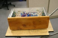
Nice shape for an amp................no!
Power rating is 100w with about 56v rails.
The amp is a high bias AB design but you can run it full class A if you lower the rails.
I use 5 pairs of outputs with low z loads but it runs fine with three pairs.
If you use R50 and 51 you can leave out R49 and leave the output stage outside the feedback loop. You could possibly run it with split feedback but I have not tried it.
I hope this helps.
Regards,
Jam
P.S. If you notice the board is laid out that you can wire it to make one pair outputs as drivers but I find thay with 20 to 40 mls of bias on the VAS it has no problem driving all five pairs of outputs.
I also wish to thank Mr.Pass and Mr.John Curl for help with design and also my good buddy MikeW(Mr.Big) for the board layout.
Nice shape for an amp................no!
Attachments
fab said:Very nice amp you did
I am working on a similar topology: current feedback jfet input and mosfet output.
jam said:Fab,
.........would you care to post details of your design?
Jam
yes, fab
come on .. dont be shy .. we know you are good
until then
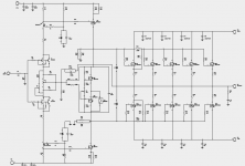
let me post MikeW jam tunes amplifier schematic
... which proves that dear jam is not only one joker
but one amplifer man, too
This design uses 5 pairs of IRFP240 + IRFP9240 for output.
And complementary cascoded JFET input stage!
Lineup
Attachments
F4 Buzquito type amp
Jam , I am really sorry I missed this post but thanks to lineup that reminded me...
Hi Lineup, thanks for your interest
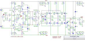
I post here one circuit I was working on. It is still in development process and should NOT be used as is...

I say "was working on" because I have switched to another one already....
see my next project at http://www.diyaudio.com/forums/showthread.php?postid=1606249#post1606249
jam said:Fab,
.........would you care to post details of your design?
Jam
Jam , I am really sorry I missed this post but thanks to lineup that reminded me...
lineup said:
yes, fab
come on .. dont be shy ...
Lineup
Hi Lineup, thanks for your interest
I post here one circuit I was working on. It is still in development process and should NOT be used as is...
I say "was working on" because I have switched to another one already....
see my next project at http://www.diyaudio.com/forums/showthread.php?postid=1606249#post1606249
Attachments
Hi MikeW, Jam,
Sorry for reviving an old thread, but your schematic is interesting (at least for me) and I'm wondering how did you solve thermal drift issues with DC-offset - if you had issues. Did you had any issues with power-on/runtime DC-offset - how fast did it settle from power-on and around which value ?
With thermal drift issues I'm referring to M3 and M6, VAS mosfets - do you have a bigger VAS idle current, such that M3 and M6 run warm-to-hot, being this way less influenced by temperature change ?
Regards,
Tibi
- Status
- This old topic is closed. If you want to reopen this topic, contact a moderator using the "Report Post" button.
- Home
- Amplifiers
- Solid State
- Jam tunes