darkfenriz said:Check out current sources and polarity of P-fet.
Hi made some change the polarity on P-fet and I add the voltage...
A.
Attachments
Re: triac?
Hi, yes the purpose of this triac is for short circuit protection.
why? is useless??
A.
fab said:Hi,
Is there a triac between the amp output and input of drive of mosfet2? if so, what is its purpose. Is it a protection and how is it suppose to work?
Thanks
Hi, yes the purpose of this triac is for short circuit protection.
why? is useless??
A.
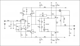
Wavebourn said:You are still forgetting about powering of left upper current sources.
He's right. At least a resistor should be put from the diodes-transistors base connection point to either ground or negative power rail.
fab said:
He's right. At least a resistor should be put from the diodes-transistors base connection point to either ground or negative power rail.
Hi, you mind this? I made some correction I hope is right...
Attachments
Latest attachment.
http://www.diyaudio.com/forums/attachment.php?s=&postid=1578825&stamp=1218000976
It might work.
But personally I woul use a little bit more current to bias the GATES of IRFP140/9140
28Volt/100kohm ~ 0.3 mA
Make those 100 kohm resistors ~27 kohm .. or even 10 kohm
Would give: ~ 1 - 3 mA
Also I would connect those bias resistors ( 100kohm / 27 kohm )
BEFORE those gate stoppers ( 47 Ohm resistors ).
If you change from 100 kohm .. to 27 kohm,
then you should make those 47 kohm (in parallel with 4.7uF) smaller, too.
Maybe like 4k7.
And those two (now 47 kohm) should be connected to GROUND.
To try and keep, hold, the output MOSFETs at zero DC Offset.
The point between those two resistors, I mean, should be connected to GND.
lineup said:Latest attachment.
http://www.diyaudio.com/forums/attachment.php?s=&postid=1578825&stamp=1218000976
It might work.
But personally I woul use a little bit more current to bias the GATES of IRFP140/9140
28Volt/100kohm ~ 0.3 mA
Make those 100 kohm resistors ~27 kohm .. or even 10 kohm
Would give: ~ 1 - 3 mA
Also I would connect those bias resistors ( 100kohm / 27 kohm )
BEFORE those gate stoppers ( 47 Ohm resistors ).
If you change from 100 kohm .. to 27 kohm,
then you should make those 47 kohm (in parallel with 4.7uF) smaller, too.
Maybe like 4k7.
And those two (now 47 kohm) should be connected to GROUND.
To try and keep, hold, the output MOSFETs at zero DC Offset.
The point between those two resistors, I mean, should be connected to GND.
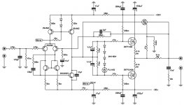
Hi, I made some change also I replaced the 1n4148 and zener whit TL431
I hope I have done all the changes correctly
A.
Attachments
xcicc said:
Hi, I made some change also I replaced the 1n4148 and zener whit TL431
I hope I have done all the changes correctly
A.
Hi, is truly terrible this project?
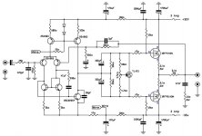
Refering to this latest schematic, in Post #11
http://www.diyaudio.com/forums/attachment.php?s=&postid=1578855&stamp=1218005389
It looks better.
1. You use 12 kohm to bias GATES of MOSFET.
2. You have put this bias BEFORE gate stopper resistors (47ohm).
3. TL431 is an excellent VBE-multiplier, to set the IDLE Current of output stage.
For these MOSFET: IRFP140N / IRFP9140N, I would try something like 250 mA idle current.
Unless you are thinking of full CLASS A operation.
Nelson Pass used almost the same output stage in his F4 amplifier.
http://www.firstwatt.com/downloads.htm
The difference may be is he is Using Full Class A Current
You may have a look at details of his setup in this document:
http://www.firstwatt.com/downloads/f4_om.pdf
what about temperature compensation for Vgs?
why set gain to +43.6dB?
why are you starting to roll off the bass from 100Hz (F-3dB=15Hz)?
22r should be 22k.
what's the purpose of 47r?
100KpF???? do you mean 100kpF=100nF?
Is 47pF in the correct location?
Why is 12k not equal to 100k?
why set gain to +43.6dB?
why are you starting to roll off the bass from 100Hz (F-3dB=15Hz)?
22r should be 22k.
what's the purpose of 47r?
100KpF???? do you mean 100kpF=100nF?
Is 47pF in the correct location?
Why is 12k not equal to 100k?
Good AndrewT.
There are some details I missed.
Most serious is of course having 12 kohm/ 100 kohm
from +30V and -30V.
Those should BOTH be the same value = 12 kohm.
About temperature sensing and VGS compensation.
Yes, this might be an issue.
But if setting the Ouput transistors fairly high biased like 250 mA or more, I think it can work well.
We are talking high current biased Class AB.
This would require also some well sized heatsinks, to reduce temperature changes to a lower level.
So, advce, when using TL431 and Class AB:
- do not use small heatsinks!
AndrewT said:what about temperature compensation for Vgs?
why set gain to +43.6dB?
why are you starting to roll off the bass from 100Hz (F-3dB=15Hz)?
22r should be 22k.
what's the purpose of 47r?
100KpF???? do you mean 100kpF=100nF?
Is 47pF in the correct location?
Why is 12k not equal to 100k?
Hi, im not sure whot I doing... im not able to calculate.... I do for experience...
22r = 22 hom
100kpF = 100.000 pf
47pf is in the correct loacation but the value is 39pf
for any suggestion you are welcome.
A.
lineup said:Good AndrewT.
There are some details I missed.
Most serious is of course having 12 kohm/ 100 kohm
from +30V and -30V.
Those should BOTH be the same value = 12 kohm.
About temperature sensing and VGS compensation.
Yes, this might be an issue.
But if setting the Ouput transistors fairly high biased like 250 mA or more, I think it can work well.
We are talking high current biased Class AB.
This would require also some well sized heatsinks, to reduce temperature changes to a lower level.
So, advce, when using TL431 and Class AB:
- do not use small heatsinks!
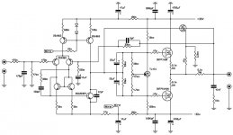
Hi, I made the changes you have suggested, I correct the mistakes and I remade the schematic and I think it is right now.
thanks
A.
Attachments
you have not got a clue to what you are trying to design. Sorry for being so blunt.xcicc said:I made the changes you have suggested, I correct the mistakes and I remade the schematic and I think it is right now.
xcicc said:Hi, I made the changes you have suggested, I correct the mistakes and I remade the schematic and I think it is right now.
thanks, A.
Two things.
1. As your resistors, capacitors and transistors have no names, it makes it difficult to speak and refer to your components in circuit.
Where is R1, R2, C1, C2, T1, T2 etc ??????
================================
2.In order to test if your circuit will work, you may simulate.
I would recommend you you download one SPICE simulator.
There are 2 freeware, which people here use:
Eagle CADSoft freeware version
http://www.cadsoft.de/freeware.htm
LTspice SwitcherCAD form Linear Technology
http://www.linear.com/designtools/software/switchercad.jsp
The 1 MOhm resistor at input, should be more like 1 kOhm.
The gain of this amplifier is
330 kohm / 220 ohm = 1500
This is too much for any power amplifier

For 2x30 Volt supply, a voltage gain of 20-30 would be more like it.
Explaination:
As the output of CD-player can be almost 1 Volt RMS
you only make amplifier work to hard, in making more then x20 or x30 for voltage gain.
( amplifier can max produce like 20 Volt RMS at output )
Regards
LineupAndrewT said:you have not got a clue to what you are trying to design. Sorry for being so blunt.
Hi, I have clear ideas, I want to build an amplifier 20W + 20W.
NO CLASS A
with distortion at maximum power less than 0,005%
Im not good in mathematics, ok.
I think that is not forbidden to mess with welder, resistors, mosfet and many explosions.

regard
A.
- Status
- This old topic is closed. If you want to reopen this topic, contact a moderator using the "Report Post" button.
- Home
- Amplifiers
- Solid State
- my new ampli mosfet