Hi all:
I'm in the process of repairing a blown power amp stage in a SWR redhead bass amp. SWR (now Fender) has been kind enough to provide the schematic (attached.) I have a few questions about the circuit design, and thought some of the folks here might be able to help.
So far, I have been able to disconnect the output stage, and temporarily stabilize the input stage by connecting NFB from the voltage amp (Q3). This showed that the input stage is all okay -- at 1V pp input, I get a nice output at Q3, about 80% of the rail and stable with low distortion. Quiescent conditions also match quite nicely with what I see in SPICE simulation.
The next step I would like to take would be to hook up the bias generator and the predriver transistors (Q7 and Q8), however, this leads to my first question...
It seems to me that the 1/2 watt 2.7K resistor upstream of the bias generator is underrated. I am assuming the bias generator will be holding 2V and change, centered around ground by NFB. That leaves about 58V (supply rails are 60V, see note on schematic) dropped across the 2.7K + 470 at the top of the bias chain. That in turn works out to almost 1W of quiescent dissipation in the 2.7K resistor. SPICE comes up with about the same result. I'd like to understand this before I hook things back up and start a small fire...")
I am also not quite sure of the function of the circuitry around Q13 and Q14. At first I thought this might be a current source or limiter for the input pair and bias chain, but it seems to me that both these transistors will be saturated under quiescent conditions?
My last question is concerning the function of the 47uF caps that connect onto the output rail. I had at first assumed these were for power rail decoupling. But the cap on the positive side here connects not to the V+ rail, but to a point partway down the bias chain, quiescent at about 9V. What are these for?
I'd really appreciate any insight offered on any of this. This is my first foray into repair on a transistor power stage (I've worked mostly with tube instrument amps to date). Its been pretty fun learning about it, and I'd be really happy to have this piece of gear working again!
cheers,
--FritzM.
I'm in the process of repairing a blown power amp stage in a SWR redhead bass amp. SWR (now Fender) has been kind enough to provide the schematic (attached.) I have a few questions about the circuit design, and thought some of the folks here might be able to help.
So far, I have been able to disconnect the output stage, and temporarily stabilize the input stage by connecting NFB from the voltage amp (Q3). This showed that the input stage is all okay -- at 1V pp input, I get a nice output at Q3, about 80% of the rail and stable with low distortion. Quiescent conditions also match quite nicely with what I see in SPICE simulation.
The next step I would like to take would be to hook up the bias generator and the predriver transistors (Q7 and Q8), however, this leads to my first question...
It seems to me that the 1/2 watt 2.7K resistor upstream of the bias generator is underrated. I am assuming the bias generator will be holding 2V and change, centered around ground by NFB. That leaves about 58V (supply rails are 60V, see note on schematic) dropped across the 2.7K + 470 at the top of the bias chain. That in turn works out to almost 1W of quiescent dissipation in the 2.7K resistor. SPICE comes up with about the same result. I'd like to understand this before I hook things back up and start a small fire...
I am also not quite sure of the function of the circuitry around Q13 and Q14. At first I thought this might be a current source or limiter for the input pair and bias chain, but it seems to me that both these transistors will be saturated under quiescent conditions?
My last question is concerning the function of the 47uF caps that connect onto the output rail. I had at first assumed these were for power rail decoupling. But the cap on the positive side here connects not to the V+ rail, but to a point partway down the bias chain, quiescent at about 9V. What are these for?
I'd really appreciate any insight offered on any of this. This is my first foray into repair on a transistor power stage (I've worked mostly with tube instrument amps to date). Its been pretty fun learning about it, and I'd be really happy to have this piece of gear working again!
cheers,
--FritzM.
Attachments
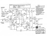
Q13/14 form a circuit which eliminates turn on/off thump, by watching for the AC waveform from the transformer disappearing. When it does, it cuts off the current source to the LTP and the bootstrap current source to the VAS, which effectively mutes the output. As long as there is AC present, both are on and Q14 connects to the +VE rail.
The top 47uF capacitor that connects with the 470R and 2K7 resistors form what is known as a bootstrap. This effectively acts as a current source for the VAS.
I must admit i've no idea what the bottom 47uF connected via 180R resistor is supposed to be doing!
The top 47uF capacitor that connects with the 470R and 2K7 resistors form what is known as a bootstrap. This effectively acts as a current source for the VAS.
I must admit i've no idea what the bottom 47uF connected via 180R resistor is supposed to be doing!
It looks like that string of components couples the output signal to the negative supply rail powering the input stage and VAS. The important thing is that I see no decoupling caps in that section of the rail (which is also isolated by the 270-ohm resistor) thus the output signal will modulate the rail voltage. Sort of “ride on top” of the DC component, so to speak. So, it looks like a bootstrap as well, aimed to increase the voltage swing of the input stage. And indeed my SPICE simulation shows that without those components the input stage will not operate nearly as perfectly or reach as high voltage swing.
amp repaired; bias recommendations?
Okay, I managed to troubleshoot and repair the output stage, so the amp is up and running now (yay!)
All that remains is to set the bias. Unfortunately, the schematic makes no mention of either calibration voltages or target quiescent currents. Also, there is not an obvious crossover distortion on my scope, even with the bias generator set to minimum bias voltage.
What are reasonable output stage quiescent currents for an amplifier like this?
thanks again,
--FritzM.
fritz email me at tetech2@doitnow.com I have the bias procedure i can email you. you will need a high power 2 ohm load and a scope to set bias correctly
- Status
- This old topic is closed. If you want to reopen this topic, contact a moderator using the "Report Post" button.
- Home
- Amplifiers
- Solid State
- SWR redhead power amp circuit questions?