Hi All I have a Crison Elektric stereo powere am that was built for me over 20 years ago boards are numbered 35 - 01B
I tried to replace the mains input plug and have messed up the wiring and now the amp takes out all the electrics from the house!
I think I have soldered one of the blue wires in the wrong place does any one have any ideas.
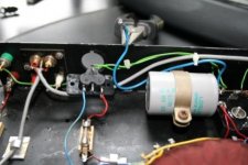
On the 3 pins from the back of the mains socket I have Earth, Live going to the fuse Nutral to the Mains transformer then there is a thicker blue cable that comes from tone of the large capicitos and I think went to the neutral but this is where I am not certain and I think is the poblem
I know the above sounds very blond but would be grateful for any assistance.
Thanks
I tried to replace the mains input plug and have messed up the wiring and now the amp takes out all the electrics from the house!
I think I have soldered one of the blue wires in the wrong place does any one have any ideas.
On the 3 pins from the back of the mains socket I have Earth, Live going to the fuse Nutral to the Mains transformer then there is a thicker blue cable that comes from tone of the large capicitos and I think went to the neutral but this is where I am not certain and I think is the poblem
I know the above sounds very blond but would be grateful for any assistance.
Thanks
I know the above sounds very blond but would be grateful for any assistance.


If your house has an earth leakage circuit breaker in the fusebox then you have almost certainly connected neutral and earth together in the amp. Neutral has a few volts on it and if connected to earth a small current will flow in the earth and this will trip your fusebox.
If you are melting real fuses then you have got more serious problems and you should ignore anything I say.
In any case, its best to give Crimson a phone call, if they still exist.
As burbeck says you should not be connecting anything from the big caps to the neutral. N should go to the transformer only.
I'm guessing, but if the blue wire from the big caps originally connected at the IEC mains connector, then it was connected to earth, not to neutral. This is in spite of the wire being blue and causing obvious confusion.
Advice
All, thanks for the advice you have been very helpful.
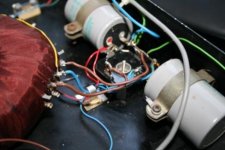
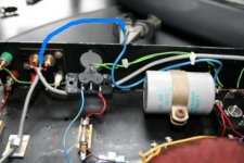
Burbeck, please see pic
The offending wire is the one that comes from the capicitor on the right of the picture and is shown held between the pliers.
I did connect it to the neutral and it took the house electrics out.
My thoughts are that perhaps it was attached to the shield of the inputs if it has not come from the back of the mains socket, but I think it was attached to the mains socket.
Thanks once agai, I would love to get it working am having a memory trip as it sounded great.
All, thanks for the advice you have been very helpful.
Burbeck, please see pic
The offending wire is the one that comes from the capicitor on the right of the picture and is shown held between the pliers.
I did connect it to the neutral and it took the house electrics out.
My thoughts are that perhaps it was attached to the shield of the inputs if it has not come from the back of the mains socket, but I think it was attached to the mains socket.
Thanks once agai, I would love to get it working am having a memory trip as it sounded great.
The turquoise A5 handbook/build manual that came with my ck1100 kit is excellent.burbeck said:the 70s eh everyone was carefree back then, Crimson's wiring diagrams were bad but not that bad.
The wiring, connectors & hardware Crimson Elektrik supplied allowed a safe build.
Well, that is all very interesting.
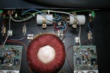
Crimson seem to like the colour blue for wiring. That transformer looks like it was hand crafted.
The thick blue wire in question connects to the star ground, the bare wire connecting the two, grey capacitors together.
What I can see suggests:
1) The transformer has a centre-tapped secondary.
2) Each pcb has a red (pos) and light blue (neg) pair of wires going to it.
3) Each pcb has a speaker wire coming from it that goes to the "red"(?) speaker terminal via a fuse
4) Each green speaker terminal connects to the star ground via a thin, green wire.
5) Each pcb has a coax from the input phono connector, both phono grounds (shields) being linked at the connectors.
6) There are two connectors in the back panel below the phono connectors, one red, one white. I can't see what these are or how they are connected. Are they alternative input connectors?
This leaves one thin, green wire and one thick, blue wire emerging from the star ground. The green is currently soldered to the mains earth on the IEC connector.
The thing that is missing is a connection between the star ground and the amp pcbs.
I can only imagine, and it makes me wince, that the shields of the input coax cables are meant to be used as the pcb connections to star ground. In which case the blue wire should connect to the phono connectors grounds. It looks like it will reach ok.
Now, why your fusebox trips is a little odd. It may be your wiring is suspect, as Andrew suggested, or it may be that the amps become unstable and draw lots of current or something without the ground connection being made. All seems pretty odd. There may be something more fundamental going on.
So, unless anyone else has a better suggestion, I would solder the blue wire to the phono ground at the phono connectors and then try it. If it still blows fuses, then I think you are stuffed without having someone look at it and measure things.
Good luck,
Brian
Attachments
To Brian
Thanks for the detailed explination the blue wire will reach the shield terminal of the inputs and the way it was carried in the amp mad me think that is in fact where it came from.
The other terminals are positive and negative for the pre amp supply but were never used for my build and remain unconnected they are just mounted on the chassis.
Will try your suggestion later this afternoon and let everyone know how I get on.
Thanks once again,
Rob
hi all.
to be fair to Crimson this most likely was a "kit amp" and was not assembled by them.
This amp is not very well put together, i would say poor from the safety side of things. some observations
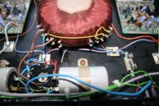
I do not see a chassis mains earth point. (the nearest to this i can see is a solder lug on one of the smothing capacitor fixing clamps, which i cannot tell if it is connected to any thing from the photo)
The tranformer screen (yellow wire) is connected to the secondary common and then to the star ground, i would like to have seen the screen connected directly to mains chassis earth point.
I would like to see the mains wiring in brown and blue with green/yellow for mains earth. no other wiring to be of the same colours.
The fuse holder would be safer if it was a better insulated type.
Mains connections should be sleeved and or double insulated.
Mains wiring/connections kept separate from everthing else, including the other wiring.
I assume the mains is fed from the pre amp, so there is no on off switch.
I do agree with traderbam with the connection point of the blue wire.
i would reccommend that the above points are corrected as well, for safety.
The issue of "taking out all the electrics from the house" did this occure when the floating blue wire was connected to Neutral? if you did this it would have been a short from Neutral to Earth which would have "took out" the Earth leakage or RCCB in the consumer unit.
I have some experience with Crimson amps particularly the kit versions and have a lot of respect for them, especially the power amps.
to be fair to Crimson this most likely was a "kit amp" and was not assembled by them.
This amp is not very well put together, i would say poor from the safety side of things. some observations
I do not see a chassis mains earth point. (the nearest to this i can see is a solder lug on one of the smothing capacitor fixing clamps, which i cannot tell if it is connected to any thing from the photo)
The tranformer screen (yellow wire) is connected to the secondary common and then to the star ground, i would like to have seen the screen connected directly to mains chassis earth point.
I would like to see the mains wiring in brown and blue with green/yellow for mains earth. no other wiring to be of the same colours.
The fuse holder would be safer if it was a better insulated type.
Mains connections should be sleeved and or double insulated.
Mains wiring/connections kept separate from everthing else, including the other wiring.
I assume the mains is fed from the pre amp, so there is no on off switch.
I do agree with traderbam with the connection point of the blue wire.
i would reccommend that the above points are corrected as well, for safety.
The issue of "taking out all the electrics from the house" did this occure when the floating blue wire was connected to Neutral? if you did this it would have been a short from Neutral to Earth which would have "took out" the Earth leakage or RCCB in the consumer unit.
I have some experience with Crimson amps particularly the kit versions and have a lot of respect for them, especially the power amps.
Reply to Birbeck
Yes the electrics were taken out when I connected the floating blue to the neutral.
The amp was a kit one but it was not assembled by me but by a electronic engineer that worked for the ILEA repairing all school media kit! alarming.
Am about to pt the blue to the screen of the inputs and assuming the electrics work I'll post back.
Thanks again Bob et all,
Rob
- Status
- This old topic is closed. If you want to reopen this topic, contact a moderator using the "Report Post" button.
- Home
- Amplifiers
- Solid State
- Crimson Elecktric Power Amp Wiring