Hi All�@!
I tried a circuit using OP amp for 1st stage, and Addition integration type�@DC servo�@....
http://www2.plala.or.jp/puthoff/amp5.html
It is recently study.
In case�@‚QVp-p sin wave 8ohm load, -3dB about 1MHz.
Sorry, it's text is only Japanese ,but I think the circuit is ‚”he world commonness...
Sincerely
Hi
Interesting circuit, I like it.") J-fet's really are great, are they not? One very minor thing, why did you use the higher voltage devices (2SC1845/2SA992) for the amplifying transistors and the lower voltage ones (2SC1815/2SA1015) designed for "linear Hfe" as the cascode? Or are these not the devices you reference in your circuit. Wouldn't you want the more linear devices for the amplifying transistors and the lower Ccob transistor for the cascode?
J-fet's really are great, are they not? One very minor thing, why did you use the higher voltage devices (2SC1845/2SA992) for the amplifying transistors and the lower voltage ones (2SC1815/2SA1015) designed for "linear Hfe" as the cascode? Or are these not the devices you reference in your circuit. Wouldn't you want the more linear devices for the amplifying transistors and the lower Ccob transistor for the cascode?
As for the circuit, I may have to experiment a bit with that J-fet set-up you got there
Interesting circuit, I like it.
J-fet's really are great, are they not? One very minor thing, why did you use the higher voltage devices (2SC1845/2SA992) for the amplifying transistors and the lower voltage ones (2SC1815/2SA1015) designed for "linear Hfe" as the cascode? Or are these not the devices you reference in your circuit. Wouldn't you want the more linear devices for the amplifying transistors and the lower Ccob transistor for the cascode? As for the circuit, I may have to experiment a bit with that J-fet set-up you got there
Thanks !
Thank you for your Reply.
J-fet is (thar is the first stage of input) square characteristic ,and
to stabilize to the temperature change than the transistor.
�@Moreover, the transistor thinks that the influence is a little even if it uses it by 0 biases of FET in the idling current in my impression while tone quality is changeable.
�@The second stage 2SC1845/2SA992 ,I tested
A970/C2240,A1145/C2705,A1015L/C1815,A1191/C2856,A1358/C3421,and(FET)213/J76,K2013/J313(this so large imput cap) is good result.. if it does as the current etc. but,they are the best,2SC1845/2SA992 Finally, it decided it by hearing however.
The cascode 2SC1815/2SA1015 "linear Hfe" is..just you said,
The idea when other people produce it. thinking good obtained one.(but only 2SC1845/2SA992 are useing..) I tried A1145/C2075,think not so difference.(Cascode it's input is Emitter�@think not so influence)
Though it is a supplementation,
the input buffer LME49710 ,MAX410EPA is good result but it's 5V one..
Though K1529/J200 the Source resistance is less,there is no ploblem in my case.
�@
The 1st stage to which necessary deflection for error margin amplification is reduced with OPamp, that LM4562 ,AD8620
is good result,too.
Constant Power supply
Addition integration type�@DC servo
Sincerely
Hi
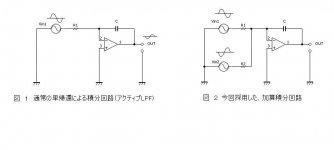
Fig 1 (left) is nomaly Active LPF.
Fig 2 (right) is Addition integration type�@DC servo,
This AMP circuit is inverted (and Current feedback) type.
so input signal and output signal Phase is inverted.
Then input signal and output signal is canceled each other,
at the same time by LPF ,only offset DC is effectively extracted.
and feed backed.
Therefore, this amp is FLAT to DC Hz , with only 0.1 uF cap.
Sincerely
Hi
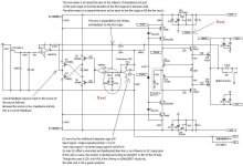
(1) 22K-470K is for ADD DC servo.
(2) 47K-2K2 is for inverted amp gain.
gain= 47K/2K2
then output signal must to be 2K2/47K time (Dividing calculation
for to be same amplitude).
In a high frequency which gain of operational amplifier becomes enough with LPF little difference is no problem,
Low frequency, each other inverted signal is cance‚Œing ,and at �@the sametime by LPF dividing)
If CAP (0.1uF) is large ,then it is OK this.
But thinking for LPF , 22K-470K.
(If this OPamp is AD8620 fet input, the register is 220K/4700K ,OK)
The data (Though it is not the one of this circuit) when it examined it before is put.
ADD type DC servo AND Normal Act LPF data
Sincerely
Hi�@Jan
This actually built, and I listens to music with this.
This circuit ,can tune oscillate with enforceable of the phase amends only in 1Kohm-2pF of A1145/C2705 at common emitter of the second step, (and under the present situation,if is not them,no problem ).
It makes it only to Coil and Register to make amends to a capacitive load of the output, this actually driving the speaker because of a rectangular wave. Compensating network of the integration type by Cap and Register .
The reason to extend the frequency response to 1MHz,
the frequency response of about 500KHz or more is given, when LME49710, OPA627, AD797, and MAX410, etc. are evaluated to the OP amp in the input buffer, this understands the difference easily and is. This is thought the influence of a county delay.
The photograph is put though only the volume of the input is different.
AMP inner photo
It makes it to the volume made of plastic contacting of the build-to-order manufacturing now. 2CP-2508-S
(The maker is Tokyo KO-ON DENPA. )
TOKYO�@KO-ON�@DENPA
Sincerely
Hi
It is an addition.
The above-mentioned volume is the one having bought it with
SANEI�@DENPA
Sincerely
It is an addition.
The above-mentioned volume is the one having bought it with
SANEI�@DENPA
Sincerely
Hi
For Study Research material.
I think it is very interesting.
ODNF (Only Distortion Negative Feedback Luxman)
this study is
http://www.ne.jp/asahi/evo/amp/odnf/odnf.htm
D-NFB
this study is
http://www.ne.jp/asahi/evo/amp/Dnfb/consider.htm http://www.ne.jp/asahi/evo/amp/Dnfb/sakadati.htm
Sincerely
For Study Research material.
I think it is very interesting.
ODNF (Only Distortion Negative Feedback Luxman)
this study is
http://www.ne.jp/asahi/evo/amp/odnf/odnf.htm
D-NFB
this study is
http://www.ne.jp/asahi/evo/amp/Dnfb/consider.htm http://www.ne.jp/asahi/evo/amp/Dnfb/sakadati.htm
Sincerely
Hi Bear !
thanks !�@
(I'm grad translation goes well)
(1)About capacitive load ,with or without,
the square wave images , the below of
http://www2.plala.or.jp/puthoff/amp5.html
, I explain.
(upperutput 1V/div,lower: input 50mV/div)
1. The Left and right (bouth)�@:Without capacitive load ,only 8 ohm resister.
The left : Input frequency is 1MHz
The right : Input frequency is 100KHz
2. The Left : without capacitive load ,only 8 ohm resister .
The right: with capacitive load(0.033ƒÊF) connected in parallel 8 ohm resister.
3. The Left : with capacitive load(0.1ƒÊF) connected in parallel 8 ohm resister.
The right: with capacitive load(1.0ƒÊF) connected in parallel 8 ohm resister.
This part was translated with above-mentioned URL.
Sincerely
thanks !�@
(I'm grad translation goes well)
(1)About capacitive load ,with or without,
the square wave images , the below of
http://www2.plala.or.jp/puthoff/amp5.html
, I explain.
(upper
utput 1V/div,lower: input 50mV/div)1. The Left and right (bouth)�@:Without capacitive load ,only 8 ohm resister.
The left : Input frequency is 1MHz
The right : Input frequency is 100KHz
2. The Left : without capacitive load ,only 8 ohm resister .
The right: with capacitive load(0.033ƒÊF) connected in parallel 8 ohm resister.
3. The Left : with capacitive load(0.1ƒÊF) connected in parallel 8 ohm resister.
The right: with capacitive load(1.0ƒÊF) connected in parallel 8 ohm resister.
This part was translated with above-mentioned URL.
Sincerely
Hi fredlock !
Thanks Reply!
It's important .
I tried with 4 ohms load (resister),but not tried with 2 ohms.
Speaker is in transitionaly change its impedance, so, under the present situation, can not drive the 2 ohms speaker, may be.
If you increase the number of output stage FET (and some treatments ,source register,gate resister..,driver transistor etc), may be able to drive 2ohms. However, it is a guess because it doesn't actually try sorry...
Sincerely
Hi bear !
Very thank you the correcting my mistakes,the "amends" to "compensation" !
I corrected the text of the explanation.
About the response of capacitive load, when decreasing the frequency response to about 300KHz , in the appearance, it is improved.(But I don't chose......)
Thanks
Sincerely
Very thank you the correcting my mistakes,the "amends" to "compensation" !
I corrected the text of the explanation.
About the response of capacitive load, when decreasing the frequency response to about 300KHz , in the appearance, it is improved.(But I don't chose......)
Thanks
Sincerely
- Status
- This old topic is closed. If you want to reopen this topic, contact a moderator using the "Report Post" button.
- Home
- Amplifiers
- Solid State
- Intro a circuit of study..