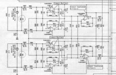
Some amps have input like this. While the input is RCA (not balanced), the receiver is configured to sense differential between + and - (like balance input receiver).
Both the + and - are passed via capacitor (E001-E002-E003-E004). The - (shield) is not connected directly to ground, but by capacitors (C021-C022)
What is the merit of doing this? Better sound? Breaking ground loop?
Why not just connect the shield of the RCA directly to ground?
Both the + and - are passed via capacitor (E001-E002-E003-E004). The - (shield) is not connected directly to ground, but by capacitors (C021-C022)
What is the merit of doing this? Better sound? Breaking ground loop?
Why not just connect the shield of the RCA directly to ground?
Attachments
The input circuit is a balanced circuit. It amplifies the difference between the two inputs. It just so happens that these two inputs are the 'hot' and 'cold' of the RCA, but it could as well be pin 2 and pin 3 of an XLR.
The advantage is that there is no direct connection between the two grounds of the source and the amp, so no possibility for ground loops that, which could set up a voltage across the ground lead, which could lead to hum etc.
Jan Didden
The advantage is that there is no direct connection between the two grounds of the source and the amp, so no possibility for ground loops that, which could set up a voltage across the ground lead, which could lead to hum etc.
Jan Didden
Another example. It's easy to short RCA shield to ground (R530=0ohm), but it is not done that way.
Janneman, if the "signal" is actually the difference between + and - , then any degradation in - (ground return) has the same effect with degradation in + ?
Janneman, if the "signal" is actually the difference between + and - , then any degradation in - (ground return) has the same effect with degradation in + ?
Attachments
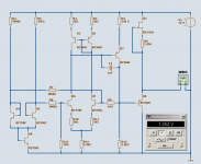
this is one discrete
differential opamp I designed.
Compares the input voltage from R7 & R8
The gain is set to 10:
- R9/R7 = 10
- R12/R8 = 10
The input differencex10 appears across R14 which refers to GROUND.
As you can see this application of my own
is one Temperature stabil 1.25 Volt Discrete Bandgap Reference.
Works very well.
Attachments
the problem with both of these circuits is that they present different impedances to ground for both +ve and -ve inputs. I think this is what lumanauw was saying. Consequently, common mode signals aren't cancelled effectively.
The imbalance added by the resistor/cap to ground is an attempt to resolve the problem caused by using a single ended, screened cable. When the source is single ended, more 50/60Hz leakage current flows in the screen than the center conductor and so the use of balanced input is broken. These are both attempts to re-direct the leakage current away from amplifier input.
Let's be honest here. A differential input only really works with a balanced output and twisted pair/screened interconnect cable.
http://www.dself.dsl.pipex.com/ampins/balanced/balanced.htm
And so, Iain:
what circuit or opamp or amplfier you use your self?
for you balanced application?
and that link to Self site,
what chapter do you refer to?
Maybe you even can refere to one of D. Self 's figures ..
My circuit published has no problems. It is for a DC output, this time.
So, if connecting reference to same point = star ground.
One leg has got 1.000.000 Ohm
One leg has got 1.003.300 Ohm
Has got no practical significations for my application.
I am not into Space Tech & I hope no other Diy Audio hobbyist is either.

Because 'our un-scientific space tech' may not meet NASA standard.
At least not yet
hehe
what circuit or opamp or amplfier you use your self?
for you balanced application?
and that link to Self site,
what chapter do you refer to?
Maybe you even can refere to one of D. Self 's figures ..
My circuit published has no problems. It is for a DC output, this time.
So, if connecting reference to same point = star ground.
One leg has got 1.000.000 Ohm
One leg has got 1.003.300 Ohm
Has got no practical significations for my application.
I am not into Space Tech & I hope no other Diy Audio hobbyist is either.
Because 'our un-scientific space tech' may not meet NASA standard.
At least not yet
hehe
Hi Lineup,
You posted as I was composing. The differential stage you show is truly differential as it hasn't been degraded by an impedance to ground on one limb.
The 470p to ground in Lumanauw's first circuit presents a 5.6Mohm impedance to ground at 60Hz which won't affect the input impedance balance very much - agreed. It will generate a significant voltage due to the leakage current flowing in the shield.
The 1K to ground in the second circuit reduces the input impedance seen by that leg to 830ohms compared to the 4.9K seen by the other leg - a significant imbalance.
But a differential input is only one part of a balanced system. You also need a balanced cable and a differential output to drive it all.
When you use RCA connectors and single conductor + shield cable, you typically have a single ended output with the shield connected to chassis at the source. The leakage capacitance to the chassis of the source is much greater than the leakage capacitance to the shielded, single ended source output and so a greater mains leakage current will flow in the shield.
You need to take a holistic approach, looking at the complete system. That was my point.
Iain McNeill said:the problem with both of these circuits is that they present different impedances to ground for both +ve and -ve inputs. I think this is what lumanauw was saying. Consequently, common mode signals aren't cancelled effectively.
The imbalance added by the resistor/cap to ground is an attempt to resolve the problem caused by using a single ended, screened cable. When the source is single ended, more 50/60Hz leakage current flows in the screen than the center conductor and so the use of balanced input is broken. These are both attempts to re-direct the leakage current away from amplifier input.
Let's be honest here. A differential input only really works with a balanced output and twisted pair/screened interconnect cable.
http://www.dself.dsl.pipex.com/ampins/balanced/balanced.htm
Ian,
David's input circuit in post # 7 *does* have equal impedances, which, as you say, is very important for CM rejection.
Edit: I overlooked the 1k. That should indeed go.
I cannot agree with you that you absolutely need a balanced output. There are two issues: equal impedances, which are essential for maximizing CM rejection, and balanced signals, which are important to maximize signal levels (and thus S/N ratio) for a given supply headroom.
But you can have great CM reduction from equal balanced impedances with SE signals, as long as you use balanced screened cable of course.
See for instance http://www.soundcraft.com/extra_product_pages/audio_balancing/index.html or the Jensen AN-003 app note.
Jan Didden
Hi Jan,
You are quite right, there are alternatives to purely balanced and single-ended. Douglas Self shows several ways of doing this:
quasi-balanced, ground canceling, superbal etc.
His website contains most, if not all, of his excellent discussion on ground loops and balanced interconnect from his books.
Hi, Janneman,
From your link above, I don't understand this part
It means connecting 75ohm resistor on +source and another 75ohm on source' output ground connected to cold/shield?
From your link above, I don't understand this part
When buzzy interference is heard, most people blame the input stage, but it doesn’t matter how good the CMRR of your input stage is if the unwanted signal on your audio cable isn’t Common Mode, so how can we make sure that it is? These airborn signals neither know nor care how the audio signal got on the two wires, what level it is or what colour the wires are, because they cannot see these things. All they know is how easily they can impress themselves onto these wires and this is entirely controlled by the Impedance that each wire presents to the unwanted signal. It is therefore essential that these two impedances are ‘balanced’ and if they are, then you have a truly Balanced Line. It is very easy to make the source impedance of the hot and cold signals equal by connecting a 75ohm resistor between the opamp output pin and the hot wire, and a matching resistor between the audio ground nearest to this opamp output and the cold wire. This is known in common parlance as Impedance Balancing, and is tremendously effective, takes no additional circuitry and is therefore the most cost effective solution.
You might be surprised to know that the vast majority of condensor microphones, including some of the most expensive on the planet, use this method. Now if this is acceptable at mic level then, Q.E.D, it must be brilliant at line level, so why use any other method?
It means connecting 75ohm resistor on +source and another 75ohm on source' output ground connected to cold/shield?
right, as in Fig. 4b here:
http://www.dself.dsl.pipex.com/ampins/balanced/balanced.htm
http://www.dself.dsl.pipex.com/ampins/balanced/balanced.htm
David,
Differential sensing of RCA inputs are done to break ground loop in noisy environments such as in vehicles especially from head unit to amplifier. This way the common mode rejection of opamp is used at its full potential by configuring the front end as instrumentation amplifier providing very high input impedance and after that conversion to single ended by differential amplifier. This is to reject any out of band noise such as hum/hiss or RF.
Differential sensing of RCA inputs are done to break ground loop in noisy environments such as in vehicles especially from head unit to amplifier. This way the common mode rejection of opamp is used at its full potential by configuring the front end as instrumentation amplifier providing very high input impedance and after that conversion to single ended by differential amplifier. This is to reject any out of band noise such as hum/hiss or RF.
Doug's site:Hi Jan,
You are quite right, there are alternatives to purely balanced and single-ended. Douglas Self shows several ways of doing this:
quasi-balanced, ground canceling, superbal etc.
His website contains most, if not all, of his excellent discussion on ground loops and balanced interconnect from his books.
http://www.douglas-self.com/
What I wonder about is the cables. What kind of RCA cables do you need and is one better then the other.
I found this about 2 years ago, but there seems to be some confusion on cables. Reason being? I don't seem to see coax style cables used in car audio. More of the twisted pair style.
It seems to make sense. But most RCA cables I have seen are simple twisted pair. Some don't even bother.
If anyone has any engerining chops to answer this in a way mere mortals would understand it? That would be really cool.
Thank you so much.
- Home
- Amplifiers
- Solid State
- Differential sensing RCA