i dlike to complain once more .....
i am from nature a very happy guy ...it really a pity that forum members are so far away from eachother and some of us if meet will make so grate things ....also find out that what i say is true ...i am a very happy guy ....i dont like to scream to people or be negative but some times i really have to !!!!!
line up :::::
except that i like you so much as a person and always read your posts since 99.9% i will learn something from them ......
why add base stopers ??? they werent in the schematic any way then your comment about variac is absolutelly wrong since when you shut down the amp and since there no input or load to it capacitor bank will act as a variac since there is no load ,rail voltage will drop and then amplifier will shelf distruct
cbs 240::::
thanks for the math ....but your calculations must be wrong since this is a WORKING AMPLIFIER !!!!! what i am trying to say is that this schematic is a clone of existing comercial HILL AUDIO CHAMELEON 900 AMPLIFIER so it was working any way ......
i will listen to all coments that might say that this amp is crappy or unstable or what ever since this is not against me but against the original designer
THE SOLUTION .......
YOU CAN CALL ME COLOUR BLIND ..... BUT I WAS PRETTY SURE THAT THE RESISTOR I USED FOR R26 R27 WAS 15K ....WELL IT WASNT ....IT ONLY LOOKED LIKE IT IT WAS 1K5 THAT WAS THE PROBLEM .....
now that we have an original working amplifier we can talk as much as you like about improovmets .....
here is a foto od the stupid resistor ....for sure looks like 15K
after all i have to thank all forum members for helping any way .....
Attachments
read the post
this is a working device clone from original schematic ......
a wonderfull 50 volts reading in my rms avc voltmeter with 80+80 volts rails under resistive load problem free up to 28500 hz .....
wg_ski said:Yes, there is a lot worng with the schematic. First off, R6 and R7 need to be some sort of thermistor or diode stack with that can be adjusted for proper bias. If you overbias it'll burn out or run away on you.
As-is, the output will be limited to +/-13V. The outputs are configured as followers the way you have them drawn. To make this simple circuit work, you need to turn the main power supply inside out. GROUND the collectors of the output transistors and take the speaker out from the center tap of the +/-79V supply. Then reverse the input phase (swap the + and - of the op amp). Do not use a TL071, it cannot provide enough drive current - the 5534 can. And the +/- supply for the op amp should remain isolated from the main supply (don't just use regulators, use a separate supply). You can boot strap it off the main supply, but that gets a little tricky if you've never done it before.
this is a working device clone from original schematic ......
a wonderfull 50 volts reading in my rms avc voltmeter with 80+80 volts rails under resistive load problem free up to 28500 hz .....
Re: read the post
Great, sakis")
was only a small resistor problem
Hehe
And me and others was doubt this amplifier is good
You were right sakis. Me was wrong.
line up :::::
except that i like you so much as a person
and always read your posts
since 99.9% i will learn something from them ......
Thanks. I learn new things from other, too.
From you, sakis, and fotios and CBS240.
why add base stopers ???
they werent in the schematic any way
then your comment about variac is absolutelly wrong since when you shut down the amp and since there no input or load to it
capacitor bank will act as a variac since there is no load,
rail voltage will drop and then amplifier will shelf distruct
Base stoppers is always normal. For good power amplifiers.
Without base stoppers is not normal.
But if you can do without. No problem. Your way!
Variac.
Well, you see those 4 resistors: those before Q1 / Q2 drivers.
Now if you turn up slowly Variac voltage,
it takes very long time when Q1/Q2 will put current into output.
But again .. if works with your Variac, I may be wrong .. again
Regards and happy you find problem. One resistor.
sakis said:this is a working device clone from original schematic ......
a wonderfull 50 volts reading in my rms avc voltmeter with 80+80 volts rails
under resistive load problem free up to 28500 hz .....
Great, sakis
was only a small resistor problem
Hehe
And me and others was doubt this amplifier is good
You were right sakis. Me was wrong.
line up :::::
except that i like you so much as a person
and always read your posts
since 99.9% i will learn something from them ......
Thanks. I learn new things from other, too.
From you, sakis, and fotios and CBS240.
why add base stopers ???
they werent in the schematic any way
then your comment about variac is absolutelly wrong since when you shut down the amp and since there no input or load to it
capacitor bank will act as a variac since there is no load,
rail voltage will drop and then amplifier will shelf distruct
Base stoppers is always normal. For good power amplifiers.
Without base stoppers is not normal.
But if you can do without. No problem. Your way!
Variac.
Well, you see those 4 resistors: those before Q1 / Q2 drivers.
Now if you turn up slowly Variac voltage,
it takes very long time when Q1/Q2 will put current into output.
But again .. if works with your Variac, I may be wrong .. again
Regards and happy you find problem. One resistor.
thats ok line up ....
i often sound like very pissed off and often kind of arrogant but really dont have bad feelings with any one .....
only thing that some times drives me mad is that people ( probably out of kindness) jump with an opinion like "change this " "change that " ....and i dont understand why should i do that on a working device .....
on the other hand you may say that this a terible working device but thats another story ....it can be discussed later ....
any way i think you are from sweden ???? are you ??? i had one of the best summers of my life in your country .....
been to broma vastervick oxelousond solna and some other places .....
amazing place and very nice people
thanks line up
As-is, the output will be limited to +/-13V. The outputs are configured as followers the way you have them drawn.
I thought this as well at first but the way the schematic is drawn had me confused. Feedback to the voltage gain stage is separated into two loops, one for Q1 & one for Q2. R16, R20 & R17, R21. The votage amplifier’s gain is 45. I doubt that using a different op-amp would affect the DC bias, but could cause oscillation. Do you have access to a scope? You could easily tell then. If the Ft of the output transistor is high, you may very well need base stopper resistors for each output transistor so it does not oscillate. Sometimes if you replace a transistor with a faster one, they tend to cause oscillations and require base resistors. You might play with the frequency of Cdom and the zero that are around the driver transistor as well to try to tame it, but you will need a scope.
As always, PCB layout is very important to stability.....

Re: thats ok line up ....
I am from Sweden.
From north part. Where is high mountains and snow .. like in north of Canada.
I do not find you agressive, sakis.
Irritated on some people's posts, yes. But you are still a good Gentleman.
There are those men, that are not gentle = not kind in manners.
But You and I and Eveybody here in forum
should be like Gentle Man with each others
There are also Gentle Woman .. but this you know I suppose
See you tomorrow, maybe.
And we talk more.
Regards to Hellas (Greece) from Sverige (Sweden)
sakis said:i often sound like very pissed off
and often kind of arrogant
but really dont have bad feelings with any one .....
--------------------
any way i think you are from sweden ???? are you ???
i had one of the best summers of my life in your country .....
been to broma vastervick oxelousond solna and some other places .....
amazing place and very nice people
thanks line up
I am from Sweden.
From north part. Where is high mountains and snow .. like in north of Canada.
I do not find you agressive, sakis.
Irritated on some people's posts, yes. But you are still a good Gentleman.
There are those men, that are not gentle = not kind in manners.
But You and I and Eveybody here in forum
should be like Gentle Man with each others
There are also Gentle Woman .. but this you know
I suppose See you tomorrow, maybe.
And we talk more.
Regards to Hellas (Greece) from Sverige (Sweden)
thats ok cbs 240 and thank you
i am cooking as we speak another version with one pair of transistors more to see how its going to be ......
your comment about base resistors has a point which i ve noticed when i made a p68 from rod elliot but with mj 15003-4 outs which have simular output configuration and up to 2outs per units all working fine but with more base resistor were required .....
i am cooking on it and let you know ...still i think another pair is not enough with 70-80 volts rails
also one thing i dont know is how critical is the rail voltage of the op amp since i am using seperate power supp for it but only brings out 14.3v per rail ( that was available) but in the schematic stated 16.5 any comments on that ????
CBS240 said:
I thought this as well at first but the way the schematic is drawn had me confused. Feedback to the voltage gain stage is separated into two loops, one for Q1 & one for Q2. R16, R20 & R17, R21. The votage amplifier’s gain is 45. I doubt that using a different op-amp would affect the DC bias, but could cause oscillation. Do you have access to a scope? You could easily tell then. If the Ft of the output transistor is high, you may very well need base stopper resistors for each output transistor so it does not oscillate. Sometimes if you replace a transistor with a faster one, they tend to cause oscillations and require base resistors. You might play with the frequency of Cdom and the zero that are around the driver transistor as well to try to tame it, but you will need a scope.
As always, PCB layout is very important to stability.....
i am cooking as we speak another version with one pair of transistors more to see how its going to be ......
your comment about base resistors has a point which i ve noticed when i made a p68 from rod elliot but with mj 15003-4 outs which have simular output configuration and up to 2outs per units all working fine but with more base resistor were required .....
i am cooking on it and let you know ...still i think another pair is not enough with 70-80 volts rails
also one thing i dont know is how critical is the rail voltage of the op amp since i am using seperate power supp for it but only brings out 14.3v per rail ( that was available) but in the schematic stated 16.5 any comments on that ????
yes of course
i know that +-15 is the standard but in this schematic there are some wierd precicness like base resistors 51R ..... and op amp 16.5 volts and so on ...there must be a reason
first i will finish with the extra transistors version so i got at least 6 per board and then will see about the details give me a couple of hours .....
i miss sverige line up ...... people were so friendlly and polite eventhough i was a "svartzcale" everywhere you go to buy cigarets for example people understand that i was a tourist and speak english to me in HOLLAND everybody was speaking dutch to me HA HA HA ( WAY TO GO JACO !!!!!! ) summer was perfect white nights and everything but also winters magic so quiet very nice i am coming there again sometime ....allready been there for 7 times from 15 -40 days per time ...really nice
ok here we go
i know it looks really terrible but working ...imagine how nice this could be on a pcb
i know it looks really terrible but working ...imagine how nice this could be on a pcb
An externally hosted image should be here but it was not working when we last tested it.
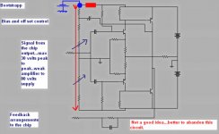
The amplifier is biased and controled by the voltage you have into the Chip output
The Dc voltage there, the potential will bias the transistors, so, it need to be precise there.
You have not off set or bias adjustment..if something is wrong, check the chip and the components you have around it.... as this one is responsable by the off set results and iddle current.
Do not tweak resistances.... the chip may be the problem...use the same suggested by the designer..do not try other ones.
To fix the problem, and to turn you able to operate this amplifier using other chips, alike the TL071 you like, you gonna need to make many changes into the feedback line, and maybe to couple the chip output using a capacitor to block DC and to to build a resistance network to bias your circuit... even a bootstrapp can be used... a series of resistances flowing current from positive to ground.... small current... from 5 to 15 miliamps flowing and calculating the voltages you gonna need into your driver input.
You will need something around 0.9 volts positive up and negative 0.9 volts into the bias resistance... audio can go using capacitor to each one of the drivers (two capacitors, one to each driver).... this bias resistance will adjust your operational point, but i am afraid you gonna face some off set problems.
I do not thing it is a good idea to explore this amplifier...it uses a chip... and the chip is the main controller..... well... this limits your range... you will not have too much room to tweak.
The small peak to peak audio level, from the chip, even if you find a good way to amplify a little, will be the limiting factor.
regards,
Carlos
Attachments
sakis
1. http://www.eastelectronics.gr/image/chameleon.jpg
very nice hand craft work .. hard wire (no pcb)
2. Sverige, Svart Skalle
& those white bright summer nights, the quiet ness of a winter landscape
I know! Sweden is a beautiful land. Very!
Swedish are a very friendly people, in general.
We are Good with tourists, yes.
Not same good with immigrants .. from Africa or Arabia
dx-amp
1. your bootstrap idea is well worth to try, destroyer = lower distortion
2. too high voltage supply is not so good .. yes, I agree, but sakis maybe not
3. feedback to chip, opamp. What is wrong with this???
Nothing!!! in my opinion.
I know several commercial Hi-Fi amplifiers using a good audio Op-Amp frontend.
And now, I speak more better Amplifiers than your DX amplifier
regars lineup
...And now, I speak more better Amplifiers than your DX amplifier
Hey, I haven't listened to the DX amp, but I like the simplistic topology. If Carlos can create good results and then duplicate them multiple times, it must be a legitimate amp design, no?.
right cbs240
he has done a VERY good work, with help of others with dx-amp
the idea is from beginning Hugh 'AKSA' Dean a friend of Carlos from Australia
but my comment wasnt against our brasilian Mr Carlos work
.. it was FOR the work of some excellent Audio power amps using Op-Amp frontend
Like this sakis Power Amplifier
I think you mis understood my message, a bit, little friend
Regards Lineup >>> Lineup Audio Labs, Sweden <<<
he has done a VERY good work, with help of others with dx-amp
the idea is from beginning Hugh 'AKSA' Dean a friend of Carlos from Australia
but my comment wasnt against our brasilian Mr Carlos work
.. it was FOR the work of some excellent Audio power amps using Op-Amp frontend
Like this sakis Power Amplifier
I think you mis understood my message, a bit, little friend
Regards Lineup
>>> Lineup Audio Labs, Sweden <<< yet again same story .....
this is a working comercial amplifier from hill audio chameleon 900..... my handwork is exact copy of the schematic ...the only thing that is diferent is that outputs are now 2SA1943 and 2SC 5200 the chip is the original as stated in the schematic NE5534 other one change but probably not importand that output resistors are now 0.27R instead of 0.22R
amplifier is working perfectly i have no wish to change anything since the amplifier is working as is but since out puts are diferent then of course bias is diferent ......
the only thing is that on idle amplifier consumes 400ma thats a lot for 75+75 rails ....and amp is boiling but otherwise working ....
can any body tell me what is exactly R26-27 doing in this circuit ???? cause when i change this from 15K to 18K ( next available ) then idle droped to 40 ma but then again clipping was kind of strange ( i presume that amp ocilates while clliping or so )
thats the only thing i want ....
or simply if there is any other way to try to drop idle to 100 ma then i will be very happy
thanks people
Re: yet again same story .....
They provide, let to input BASE, current to Q1 Q2.
Without them would be no current in Q1, Q2 & output stage.
Make resistance Bigger (18 kohm) = not so much current into BASES
Make resistance Smaller (15 kohm) = a bit more current into BASE
of Q1 and Q2 which drives the output stage HARDER
Resistors make RESISTANCE 'Movement' against Current flow, floating.
Loudspeaker wire/cable have low resistance .. so can much current drive your speakers.
A thick wire will flow much current. (0.01 Ohm) Maybe 100 Ampere.
10 MOhm R make very big resistance to current flood.
So, maybe only 0.0000001 Ampere (0.1 uA) current can go, from power.
sakis said:
what is exactly R26-27 doing in this circuit ????
cause when i change this from 15K to 18K
then idle droped to 40 ma
They provide, let to input BASE, current to Q1 Q2.
Without them would be no current in Q1, Q2 & output stage.
Make resistance Bigger (18 kohm) = not so much current into BASES
Make resistance Smaller (15 kohm) = a bit more current into BASE
of Q1 and Q2 which drives the output stage HARDER
Resistors make RESISTANCE 'Movement' against Current flow, floating.
Loudspeaker wire/cable have low resistance .. so can much current drive your speakers.
A thick wire will flow much current. (0.01 Ohm) Maybe 100 Ampere.
10 MOhm R make very big resistance to current flood.
So, maybe only 0.0000001 Ampere (0.1 uA) current can go, from power.
Re: yet again same story .....
Saki
Have you tried to add one more pair of output transistors? And leave the rest components as they are. Maybe this resolve many problems. Make an experiment.
Fotis
sakis said:this is a working comercial amplifier from hill audio chameleon 900..... my handwork is exact copy of the schematic ...the only thing that is diferent is that outputs are now 2SA1943 and 2SC 5200 the chip is the original as stated in the schematic NE5534 other one change but probably not importand that output resistors are now 0.27R instead of 0.22R
amplifier is working perfectly i have no wish to change anything since the amplifier is working as is but since out puts are diferent then of course bias is diferent ......
the only thing is that on idle amplifier consumes 400ma thats a lot for 75+75 rails ....and amp is boiling but otherwise working ....
can any body tell me what is exactly R26-27 doing in this circuit ???? cause when i change this from 15K to 18K ( next available ) then idle droped to 40 ma but then again clipping was kind of strange ( i presume that amp ocilates while clliping or so )
thats the only thing i want ....
or simply if there is any other way to try to drop idle to 100 ma then i will be very happy
thanks people
Saki
Have you tried to add one more pair of output transistors? And leave the rest components as they are. Maybe this resolve many problems. Make an experiment.
Fotis
ok line up
thank you very much ...this is exactly what i had in mind and also i am familiar with ohms laws ....but thats not the point ....
since my design scills are not enough i cannot tell what else these changes might effect .... going from 15K to 18K droped idle very much down ( still no crossover distortion ) so a value something like 16-16.5K will do the trick
i have to expirament but this or somebody has to calculate it for me and/or look for side effects
fotios ...my friend !!!!
i think when you look at a target of a cheap made machine to produce arround 300w in a cheap way then 6 outputs is almost enough then one pair more may require base resistors which is ok but also may be possible to create ocilation ( quiet comon when you drive multiple outputs).and i will not be able to locate this easily ......
so far i think i ve been lucky cause even in this protoype ive made pp hand job ...all wave forms are very very clean ( compaired to how the tests were made with two seperate trafos and rails of 2.5 mm but almost 1 m long, no zobel, no inductor and generally a cable mess ) which normally "pick" up things on the way and then drive amp to oscilation ....well not in this case
even when my "board" and set up was very messy wave forms were very very clean .....
hell !!!! i produced almost 320w at full rail voltage almost 80v and i had a very clean sine wave on my scope while with the same messy set up a legend 4 mosfet amp with 40+40 volt rails and almost 100w power was oscilating cause it didnt like one earth loops created by the interconnects of power between my signal genarator and the scope ....amazing !!!!!
- Status
- This old topic is closed. If you want to reopen this topic, contact a moderator using the "Report Post" button.
- Home
- Amplifiers
- Solid State
- help wanted in this schematic